
Method for circularly trapping SO2 and CO2 by using calcium-based absorbent

A calcium-based absorbent, fluidized bed technology, applied in the field of calcium-based absorbent to capture sulfur dioxide and carbon dioxide, can solve the problems of increasing economic cost, increasing the input of calcium-based absorbent, affecting carbonation reaction, etc. Reduce system energy consumption and economic cost, good technical economy, avoid the effect of input

Inactive Publication Date: 2010-08-11
SHANDONG UNIV
View PDF0 Cites 32 Cited by
  • Summary
  • Abstract
  • Description
  • Claims
  • Application Information

AI Technical Summary

Problems solved by technology

[0007] SO in flue gas has been confirmed in a small bubbling fluidized bed 2 The presence of CaO accelerates the capture of CO by the cycle 2 The attenuation of performance, the sulfation product layer formed on the surface of CaO seriously affects the carbonation reaction
Experiments show that only CO capture with limestone 2 Compared to simultaneous capture of SO in limestone 2 and CO 2 , even if SO 2 Very low concentration, such as 100ppmv, will also significantly reduce the carbonation conversion rate of limestone
Thanks to SO 2 CO capture on calcium-based absorbents 2 The serious hindrance effect brought by performance, coal-fired power station in order to ensure to maintain a high CO 2 The collection efficiency has to increase the input of calcium-based absorbent. The circulation of a large amount of calcium-based absorbent in the reactor not only increases the operating cost and energy consumption in the calcination process, but also causes the wear, fouling and Increased corrosion
Especially in the use of artificially prepared highly active calcium-based absorbents with high economic costs for cyclic capture of CO 2 when SO 2 The existence of the active absorbent will seriously inactivate and increase the economic cost

Method used


Image

  • Method for circularly trapping SO2 and CO2 by using calcium-based absorbent
  • Method for circularly trapping SO2 and CO2 by using calcium-based absorbent

Examples


Embodiment Construction

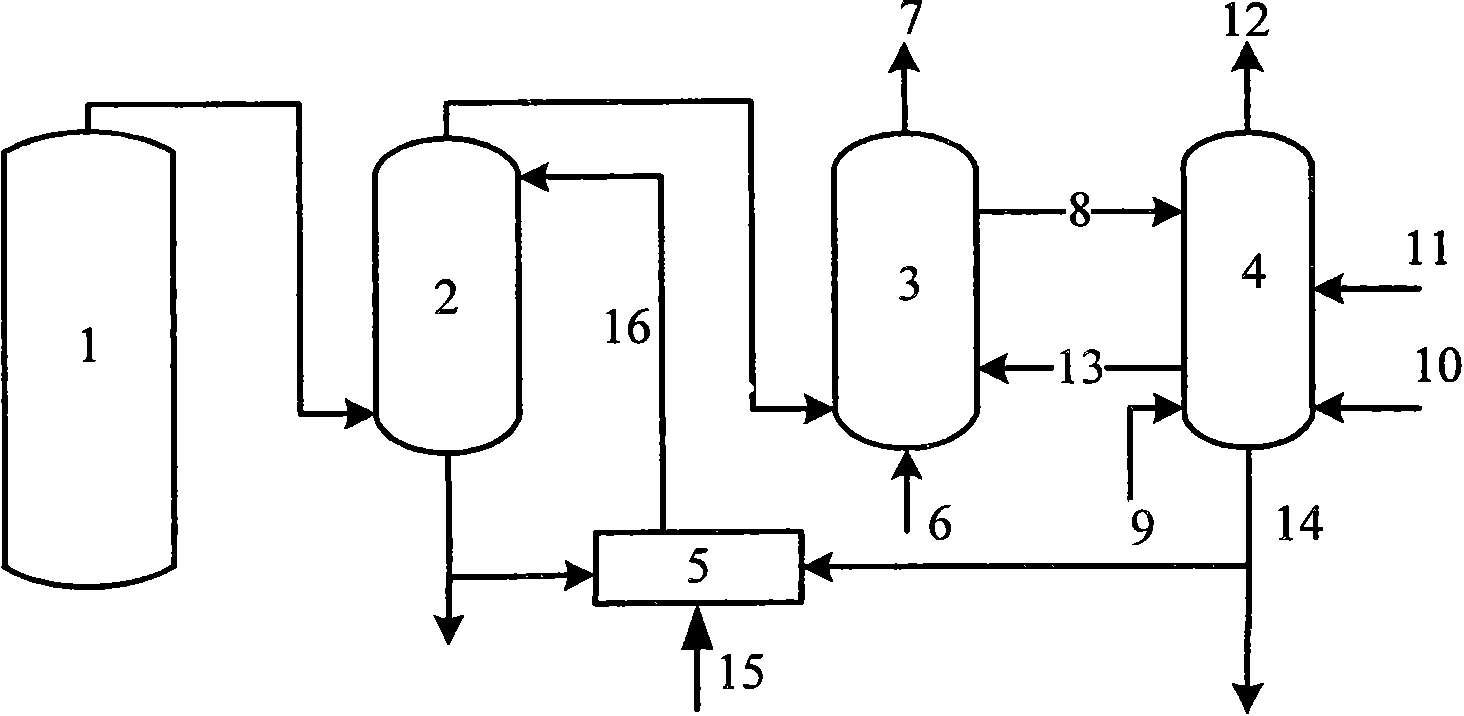
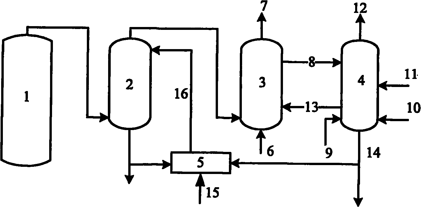
[0021] Such as figure 1 As shown, the flue gas produced by the pulverized coal furnace 1 of the power station is desulfurized by the desulfurization tower 2, and then enters the fluidized bed carbonation reactor 3, and the CO 2 CO in flue gas7 after being captured 2 The content of CaO is very low and can be directly discharged into the atmosphere. In the fluidized bed carbonation reactor 3, CaO generates solid Ca(OH) under the action of steam 6 from the steam turbine. 2 , the molar ratio of CaO13 to water vapor 6 is 1.2. Ca(OH) 2 Particles undergo carbonation reaction to capture CO 2 , the reaction temperature is 280-300°C, and the product is CaCO 3 8 and water vapor. CaCO 3 8 into the fluidized bed calciner 4 for calcination, using the heat generated by the oxygen-enriched combustion of biomass fuel 10 to make the CaCO 3 8 decomposed into CaO and CO 2 , the calcination temperature is 900-950°C, CaO13 is introduced into the fluidized bed carbonation reactor 3 to captur...


PUM


Abstract

The invention provides a method for trapping SO2 and CO2 on a large scale aiming at a pulverized coal furnace of a power plant. Fume generated by the pulverized coal furnace of the power plant is desulfurized by a desulfurizing tower and then enters a fluidized bed carbonation reactor; CaO in the reactor generates solid Ca(OH)2 under the action of water vapor; Ca(OH)2 particles are subjected to a carbonation reaction to trap CO2; a product CaCO3 enters a fluidized bed calcining furnace; the CaCO3 is decomposed into CaO and CO2 by using the heat generated by oxygen enriched combustion of a biomass fuel; and the CaO is introduced into the carbonation reactor for trapping the CO2 to realize the recycling. The inactive CaO is discharged from the lower part of the fluidized bed calcining furnace, and meanwhile, the calcium-based absorbent is supplemented. Part of inactive CaO discharged from the calcining furnace is introduced into a digestion reaction to form a Ca(OH)2 solution and then enters the desulfurizing tower for desulfurization, so that the respective removal of the SO2 and the CO2 can be realized and the energy consumption of the system can be reduced.

Description

technical field [0001] The invention relates to a method for circularly capturing sulfur dioxide and carbon dioxide by a calcium-based absorbent, and belongs to the technical field of environmental pollution prevention and clean coal combustion. Background technique [0002] increasing CO 2 Emissions are the main cause of global warming. Coal CO 2 The largest emissions, while coal power is the most concentrated CO 2 Stationary emission source, so it is considered as the main CO 2 emission reduction target. Calcium-based Absorbent Cyclic Calcination / Carbonation Reaction for CO Capture 2 Due to the use of cheap and abundant resources such as limestone and dolomite as CO 2 Absorbent has good technical economy, which has attracted extensive attention of scholars from all over the world in recent years. [0003] Calcium-based Absorbent Cyclic Calcination / Carbonation Reaction for CO Capture 2 technology is currently an effective way to control CO 2 emission technology. C...

Claims


Application Information

Patent Timeline
IPC IPC(8): B01D53/75B01D53/50B01D53/62
CPCB01D2257/504B01D2251/404Y02A50/20
Inventor 李英杰路春美韩奎华赵建立王永征程世庆
Owner SHANDONG UNIV
Learn More