
Measuring device and method of optical fibre transmission loss factor

A loss factor, optical fiber transmission technology, used in testing optical performance and other directions

Inactive Publication Date: 2011-04-20
SHANGHAI JIAO TONG UNIV
View PDF0 Cites 1 Cited by
  • Summary
  • Abstract
  • Description
  • Claims
  • Application Information

AI Technical Summary

Problems solved by technology

[0005] The present invention aims at the above-mentioned deficiencies existing in the prior art, and provides a kind of optical fiber transmission loss coefficient measurement device and measurement method, which overcomes the existence of destructive operation in the measurement of optical fiber transmission loss coefficient by the cutting method and the influence of the insertion loss method on the measurement of the coupling connector. The result is inaccurate, and it is different from the general OTDR based on the backscattering method, which uses a high-power narrow pulse optical signal to measure the fiber loss. It uses a wider square wave laser pulse signal as the fiber input signal, which greatly reduces the backscattering. Influence of mode distribution of scattered light and inhomogeneity of optical fiber on measurement results

Method used


Image

  • Measuring device and method of optical fibre transmission loss factor
  • Measuring device and method of optical fibre transmission loss factor
  • Measuring device and method of optical fibre transmission loss factor

Examples


Embodiment Construction

[0025] The following is a detailed description of the embodiments of the present invention. This embodiment is implemented on the premise of the technical solution of the present invention, and detailed implementation methods and specific operating procedures are provided, but the protection scope of the present invention is not limited to the following implementation example.

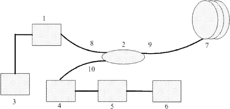
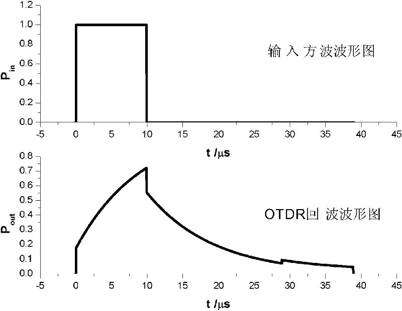
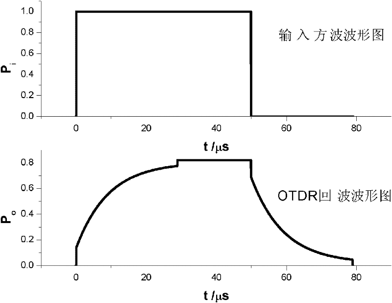
[0026] like figure 1 As shown, this embodiment includes: a laser emitting device 1, a three-port circulator 2, a function signal generator 3, a photodetector 4, a digital oscilloscope 5, a computing function module 6 and a measured optical fiber 7, wherein: the function signal generator 3. Connect with the laser emitting device 1 and modulate the output laser into a square-wave optical pulse. The laser emitting device 1 is connected with the first port 8 of the three-port circulator 2 and output the square-wave optical pulse. The second port of the three-port circulator 2 9 is connected with the optic...


PUM


Abstract

The invention relates to back scattering method based measuring device and method of an optical fibre transmission loss factor, belonging to the technical field of optical fibre measurement. The measuring device comprises a laser emitting device, a three-port circulator, a function signal generator, a photoelectric detector, a digital oscilloscope and a computing function module. The invention solves the problems of destructive operation in a cutting-off method measuring the optical fibre transmission loss factor and inaccurate measurement result in an insertion loss method affected by a coupled connector, is different from a general method for measuring optical fibre loss by adopting a high-power narrow-pulse optical signal on the basis of the optical time domain reflectometry (OTDR) of the back scattering method, greatly reduces the influences of the mode distribution of back scattering light and the nonuniformity of optical fibers on a measurement result by using a wider square-wave laser pulse signal as an optical fibre input signal, and has simple device, easy and convenient operation and accurate measurement result.

Description

technical field [0001] The invention relates to a method in the technical field of optical fiber measurement, in particular to an optical fiber transmission loss coefficient measurement device and measurement method based on a backscattering method. Background technique [0002] The transmission loss characteristic of optical fiber is one of the most important factors that determine the transmission distance, transmission stability and reliability of optical fiber network, so it is of great significance to accurately measure the transmission loss coefficient of optical fiber. In optical fiber communication, the transmission loss of optical signals in optical fibers mainly includes splicing loss (inherent loss of optical fiber, fusion splicing loss and active joint loss) and non-splicing loss (loss caused by bending loss, other construction factors and application environment) kind. [0003] There are three methods for measuring the optical fiber transmission loss coefficien...

Claims


Application Information

Patent Timeline
Patent Type & Authority Patents(China)
IPC IPC(8): G01M11/02
Inventor 吴至境沈启舜袁文陆徐超刘天元
Owner SHANGHAI JIAO TONG UNIV
Learn More