Direction-injection diesel engine combustion chamber
A combustion chamber and diesel engine technology, applied in combustion engines, mechanical equipment, engine components, etc., can solve problems such as high HC and CO emissions, increased fuel injection, poor evaporation, etc., and achieve the effect of reducing NOx and particulate emissions
- Summary
- Abstract
- Description
- Claims
- Application Information
AI Technical Summary
Problems solved by technology
Method used
Image
Examples
Embodiment Construction
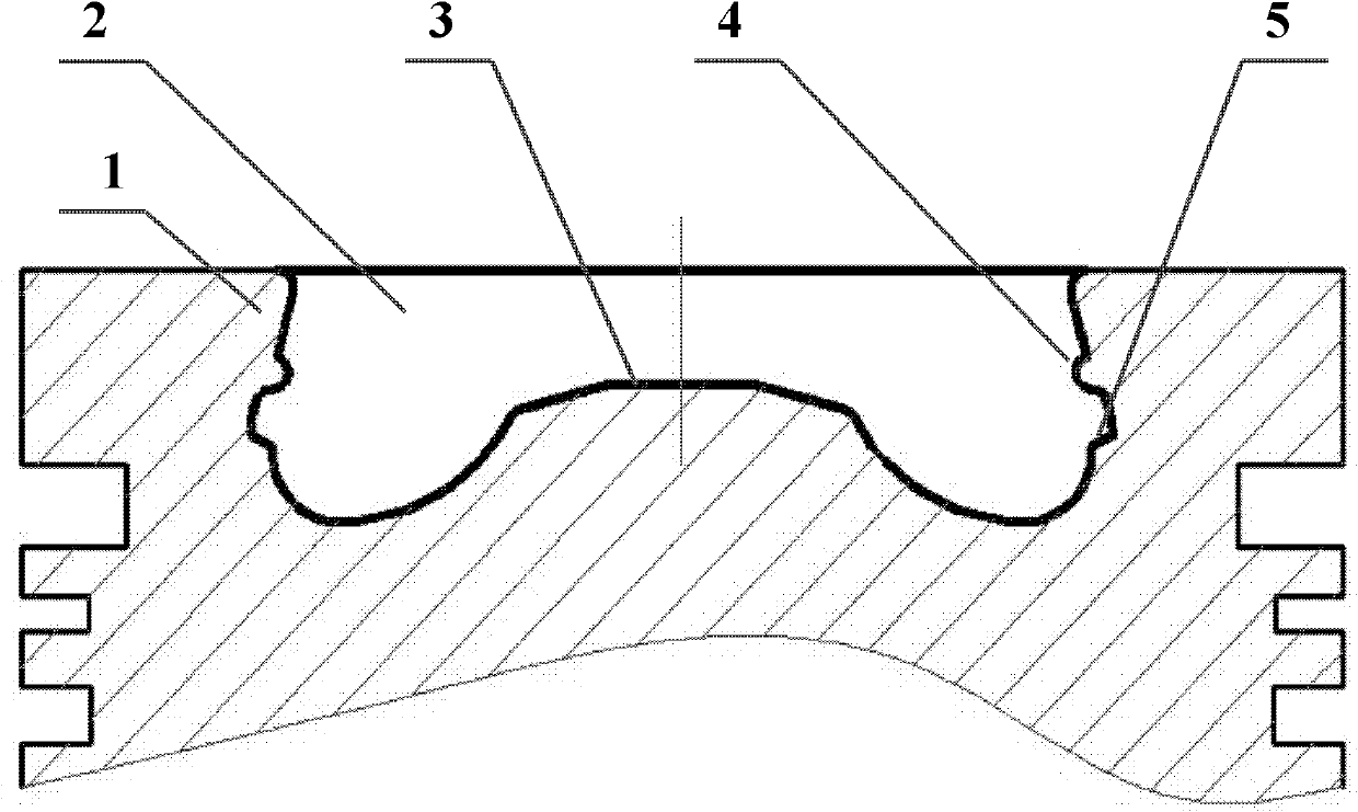
[0017] exist figure 1 Among them, the combustion chamber 2 of the present invention is on the piston 1, and it is characterized in that the inner wall of the combustion chamber 2 is provided with guide convex arcs 4 and small steps 5 in the circumferential direction, and the bottom surface 3 is a boss type (the bottom surface 3 can also be designed as a cone, flat bottom, spherical, etc.). from figure 1 It can be seen from the figure that the combustion chamber 2 is in the shape of a shrinking mouth, and it can also be designed as a straight mouth or an open mouth.
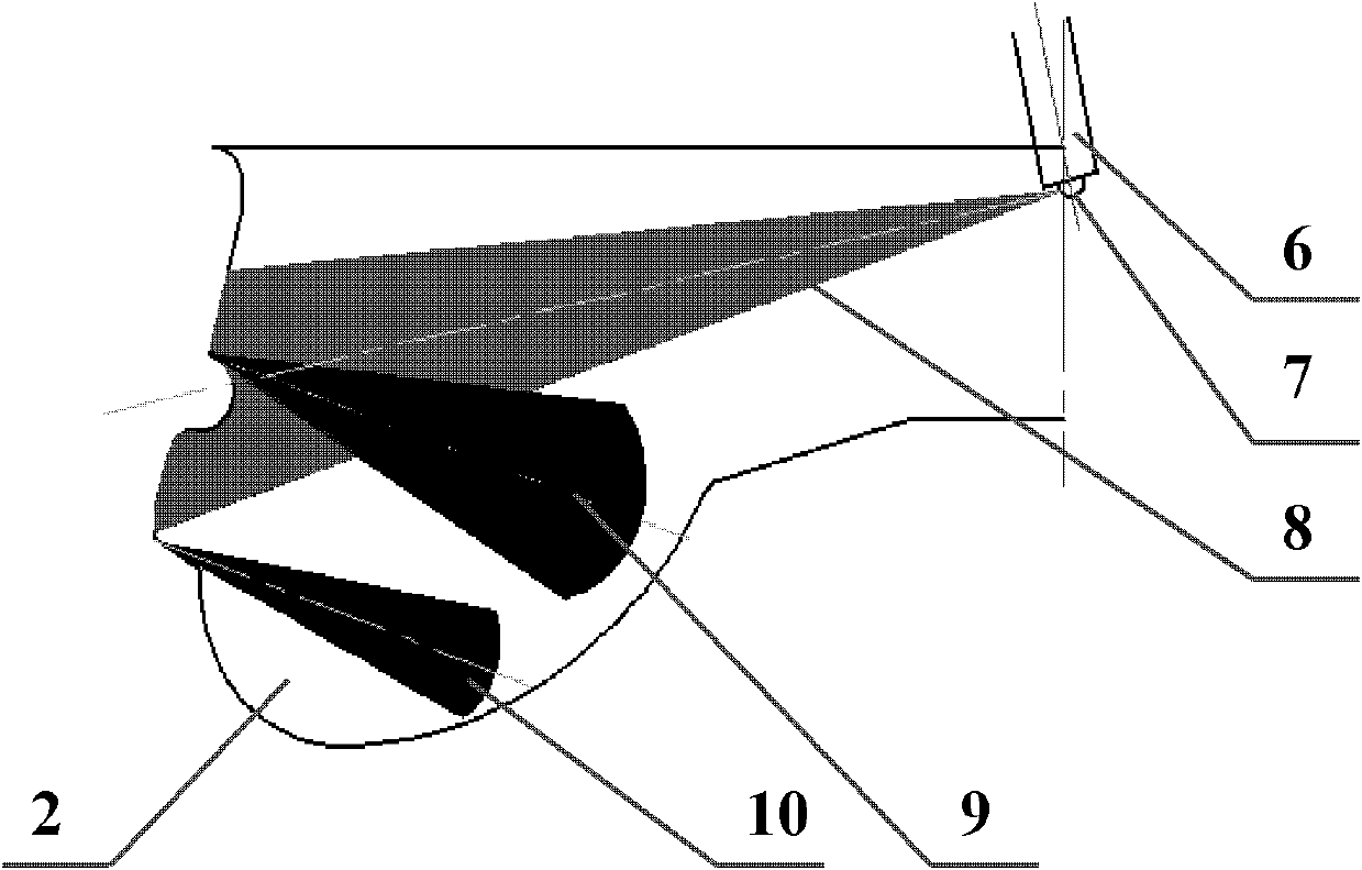
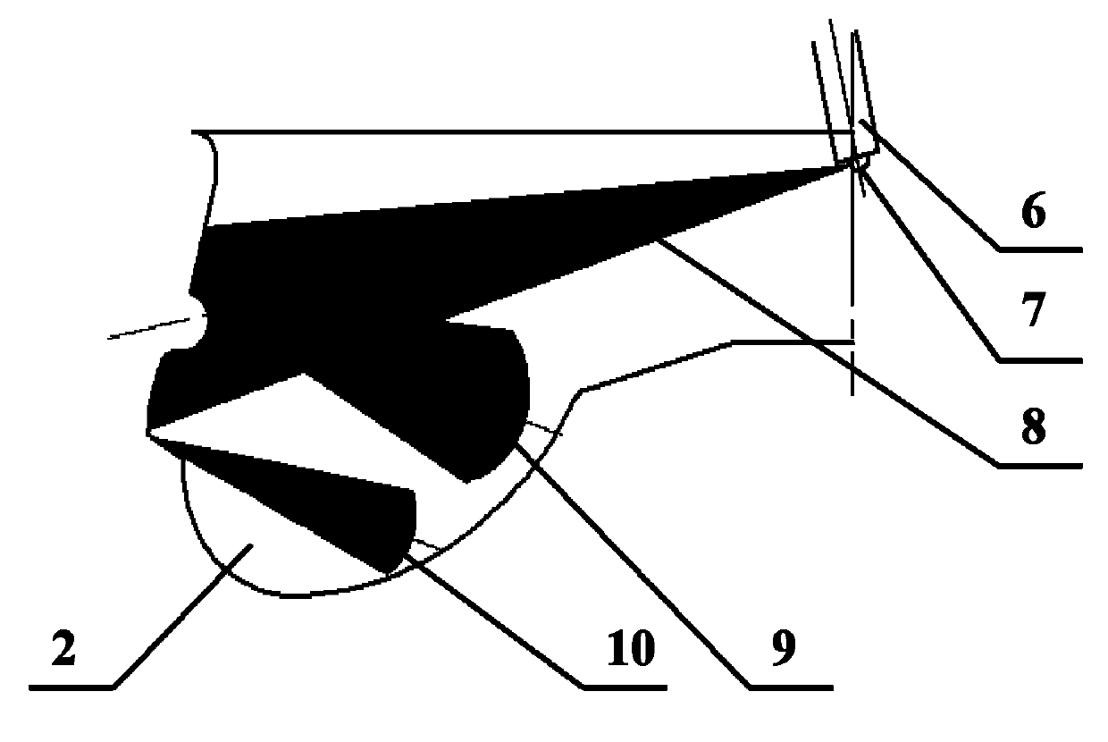
[0018] The liquid oil beam 8 sprayed out by the porous injector hits the wall of the combustion chamber 2, and is reflected by the guiding convex arc 4 and the small step 5 on the wall to form the upper jet 9 and the lower jet 10 of the layered wall jets. , referred to as "double wall jet", such as figure 2 shown.
[0019] The spray jet 8 (single or multiple injections) ejected from the multi-hole injector 6 ...
PUM
 Abstract
Description
Claims
Application Information
 - R&D
- Intellectual Property
- Life Sciences
- Materials
- Tech Scout
- Unparalleled Data Quality
- Higher Quality Content
- 60% Fewer Hallucinations
Browse by: Latest US Patents, China's latest patents, Technical Efficacy Thesaurus, Application Domain, Technology Topic, Popular Technical Reports.
© 2025 PatSnap. All rights reserved.Legal|Privacy policy|Modern Slavery Act Transparency Statement|Sitemap|About US| Contact US: help@patsnap.com


