
Method for material removal and device for carrying out said method

A technology of cutting line and cutting depth, which is applied in welding equipment, laser welding equipment, metal processing equipment, etc., and can solve problems such as limiting quality

Inactive Publication Date: 2010-07-21
FRAUNHOFER GESELLSCHAFT ZUR FOERDERUNG DER ANGEWANDTEN FORSCHUNG EV
View PDF0 Cites 14 Cited by
  • Summary
  • Abstract
  • Description
  • Claims
  • Application Information

AI Technical Summary

Problems solved by technology

Phenomena of groove and burr formation limit quality

Method used


Image

  • Method for material removal and device for carrying out said method
  • Method for material removal and device for carrying out said method
  • Method for material removal and device for carrying out said method

Examples


Embodiment Construction

[0095] As already explained, unnecessarily large fluctuations of the cutting parameters that exceed the dimensions of unavoidable fluctuations and are reflected in the groove pattern are to be recognized as avoidable fluctuations and at least such fluctuations should be reduced.

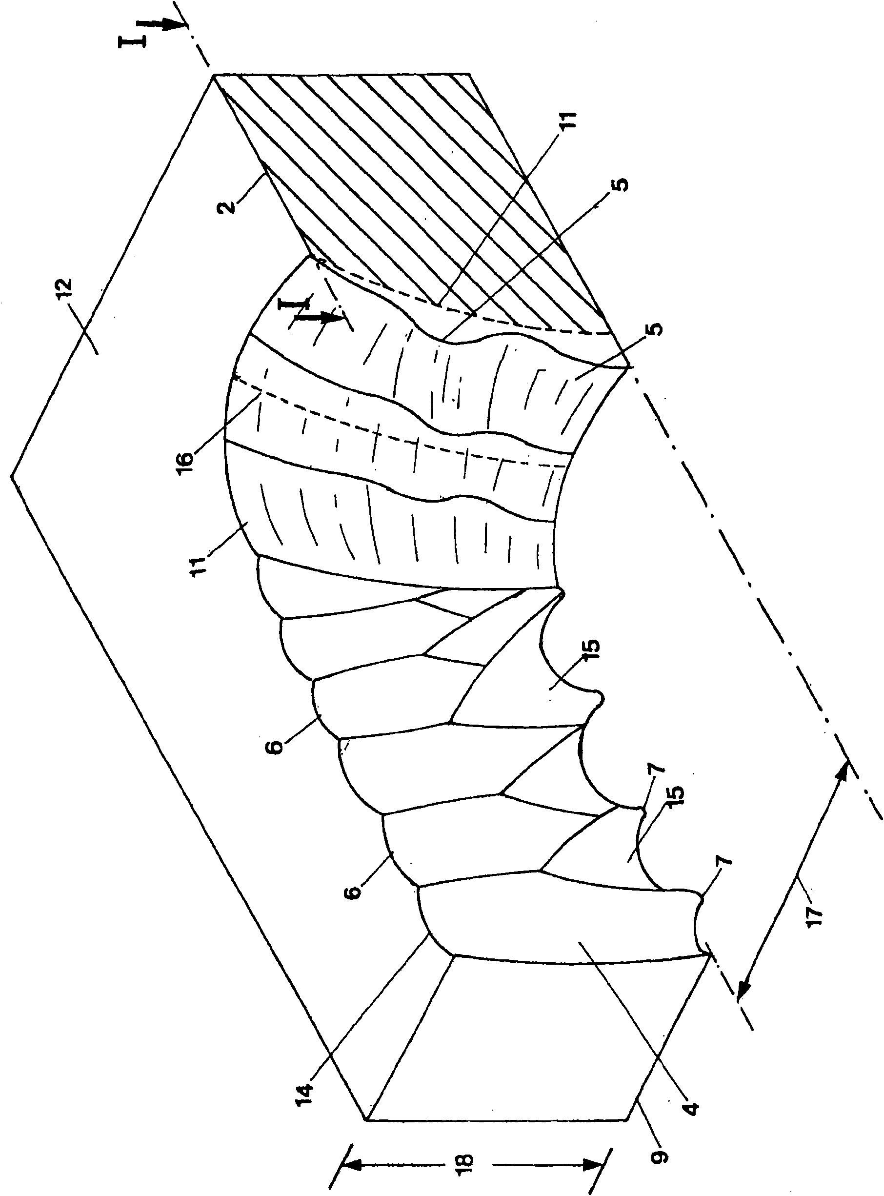
[0096] figure 2 A cut 1 produced by means of a laser beam along a cutting line I-I (reference number 2 ) in a workpiece 3 is schematically shown. The cutting of the material in the incision 1 takes place by melting the workpiece material, possibly also by vaporizing it, with the aid of a gas jet surrounding the laser beam. The gas jet can be reactive or also inert with respect to the workpiece material.

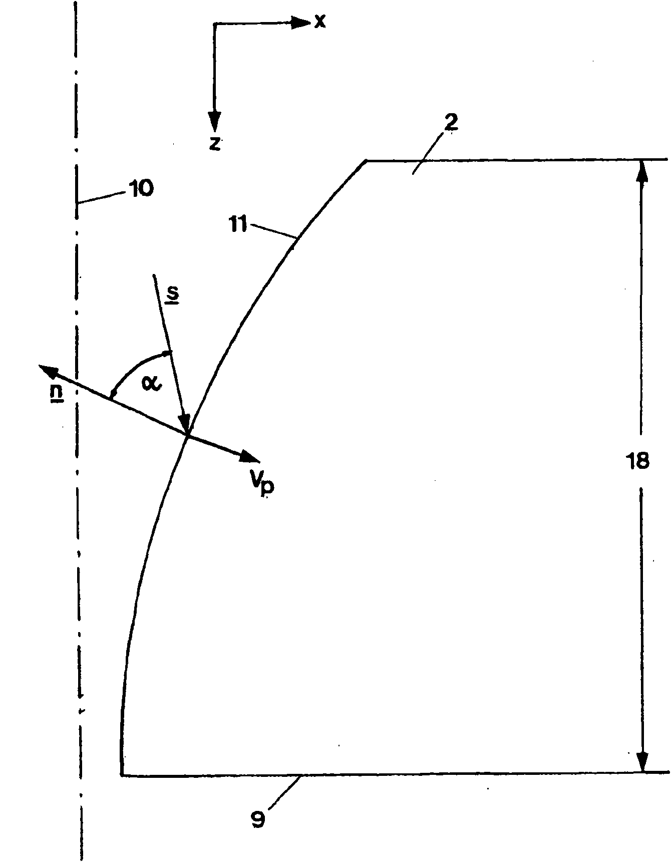
[0097] Incision 1 has two cutting edges or cutting edges 4 (in figure 2 Only one of the cutting edges can be seen in the "half cut" of the cutting edge) and the cutting seam of a cutting front face 11. As a rule, the cutting edge or cutting edge 4 exhibits a groove 6 with more or less straightf...


PUM


Abstract

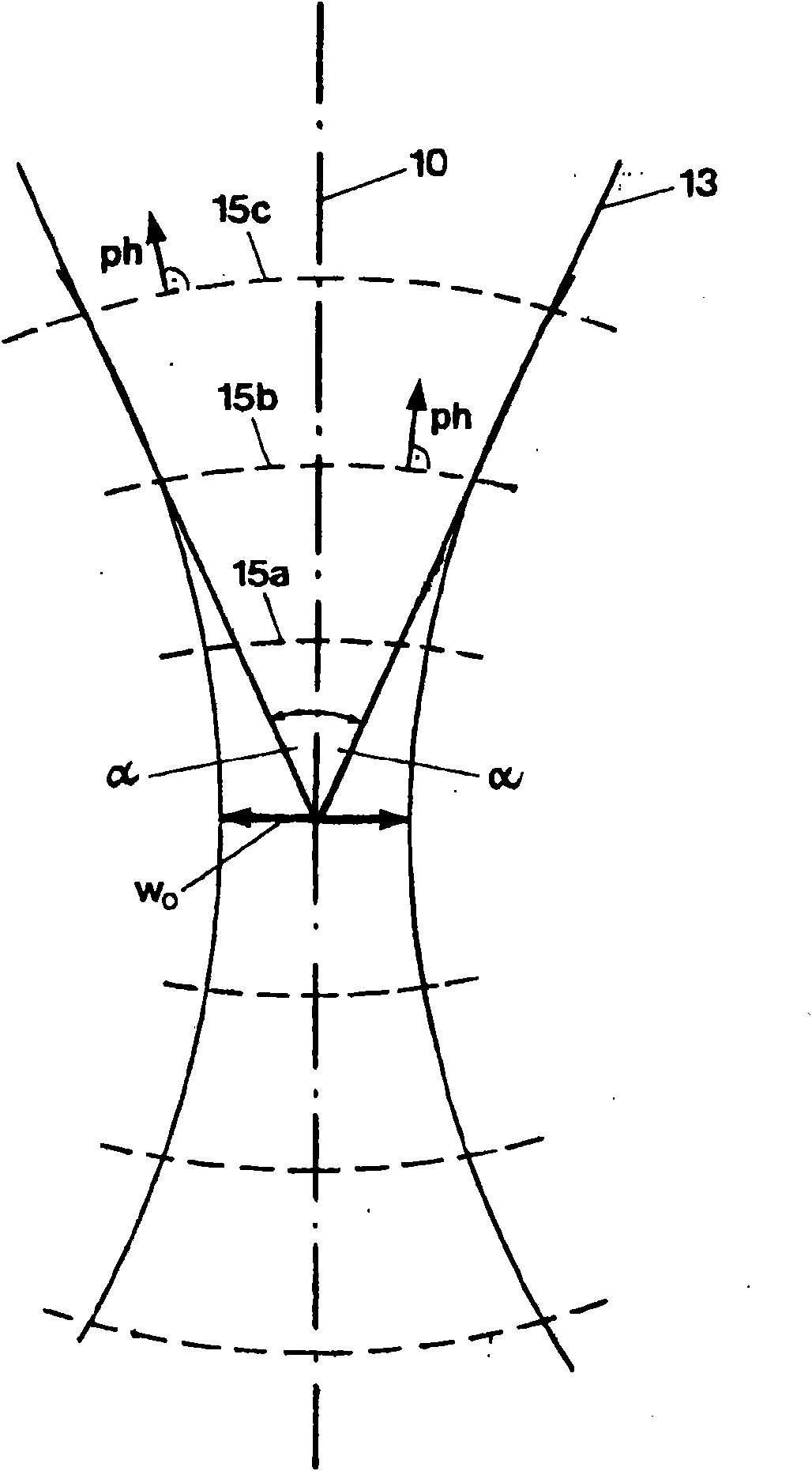
The invention relates to a method for the material removal to a predetermined removal depth from a workpiece by means of a laser beam consisting of one or more sub-beams, each of the latter having a defined beam axis. The axis of the laser beam or the individual axes of the sub-beams are guided along a removal line at a predetermined travelling speed and the laser beam has a predetermined spatialenergy flow density that defines a Poynting vector S with a value Iof(x) and a direction s, the spatial energy flow density creating a removal face with an apex formed by the leading part of the removal face in the removal direction and said face creating a removal edge. The method is characterised in that the respective incident angles alpha of the removal face, formed by the normal vectors n atthe removal face and the directions s of the Poynting vectors are set in such a way that they do not exceed a maximum value alphamax in a predefined region around the apex of the removal face. If themaximum value is exceeded, this is detected in the change from a small groove amplitude in an upper part of the removal edge to a large groove amplitude in a lower part of the removal edge. The invention also relates to a device for carrying out said method.

Description

technical field [0001] The invention relates to a method for removing material within a predetermined cutting depth range of a workpiece by means of a laser beam consisting of one or more partial beams each having a defined beam axis, The axes of the laser beam or the individual axes of the partial beams are guided jointly along the cutting line at a predetermined travel speed and the laser beam has a power flow with a predetermined spatially defined Poynting vector S density, the energy flux density has the value I 0 f(x) and direction s, wherein the energy flux in the space produces a cutting front with a top as the furthest part of the cutting front in the cutting direction, with which a cutting edge is produced. Furthermore, the invention relates to a device for carrying out the method. Background technique [0002] Laser cutting is an approved method for material removal by melting, in which the depth of cut produced includes the total thickness of the workpiece. Whe...

Claims


Application Information

Patent Timeline
Patent Type & Authority Applications(China)
IPC IPC(8): B23K26/38
CPCB23K26/38B23K26/0617B23K26/0604
Inventor W·舒尔茨D·佩特林F·施奈德M·尼森
Owner FRAUNHOFER GESELLSCHAFT ZUR FOERDERUNG DER ANGEWANDTEN FORSCHUNG EV
Learn More