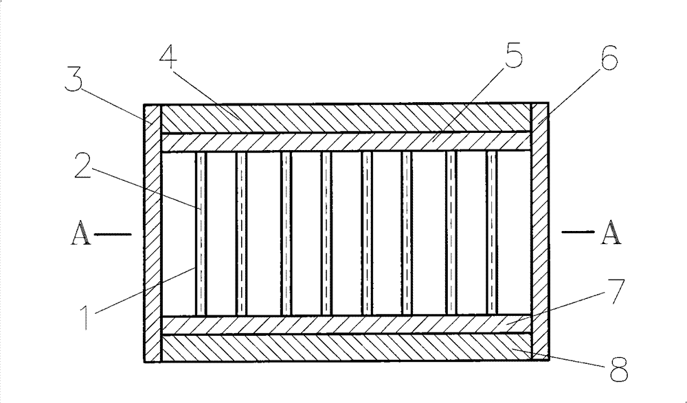
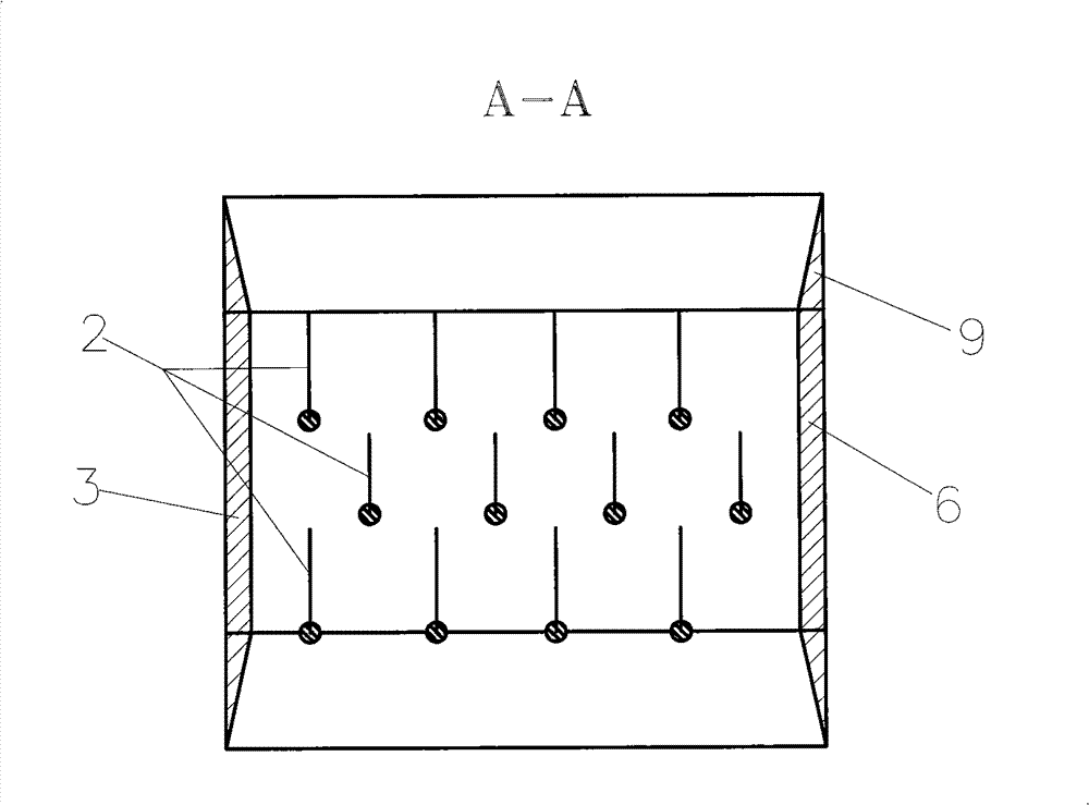
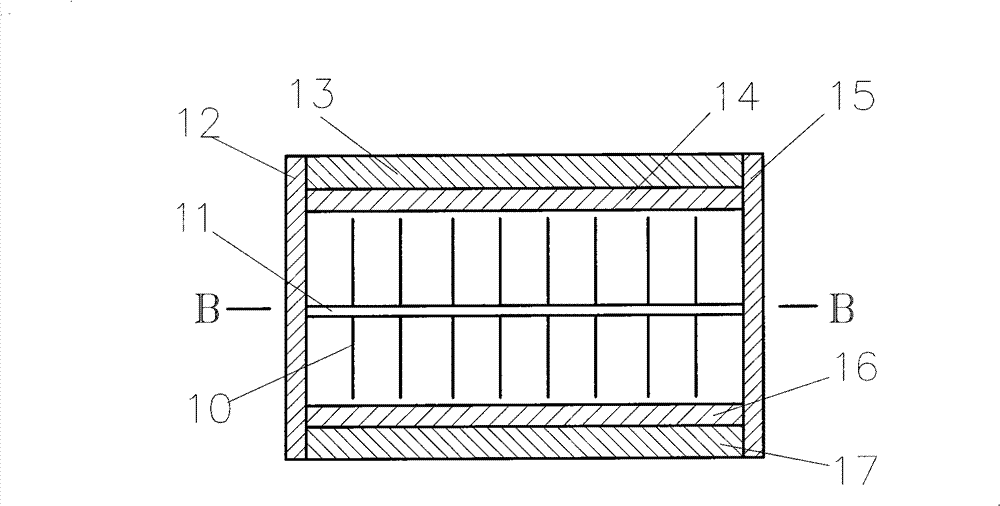
Chatter wind power generation apparatus

A technology of wind power generation device, resistance, applied in the field of tremor wind power generation device

Inactive Publication Date: 2013-05-01
刘新广
View PDF4 Cites 0 Cited by
  • Summary
  • Abstract
  • Description
  • Claims
  • Application Information

AI Technical Summary

Problems solved by technology

However, the prior art manufactures wind power generators, and the manufacturing cost of the generator and fan blades is high
For large and medium-sized wind power generators and large and medium-sized wind power stations, due to the length of the wind rotor blades (one or two meters short and tens of meters long), the generator driven by the wind wheel is heavy, and the tower for installing the wind wheel and the generator is too heavy. Therefore, it is difficult to manufacture wind rotors, generators, and towers, and transportation and installation are difficult. Heavy equipment and heavy vehicles are necessary. Therefore, manufacturing wind turbines and building wind power stations with existing technologies is more expensive and difficult to maintain. , take up a lot of space

Method used


Image

  • Chatter wind power generation apparatus
  • Chatter wind power generation apparatus
  • Chatter wind power generation apparatus

Examples


Embodiment 1

[0032] Embodiment three: as Figure 5 Figure 6 Show. On the upper surface of the magnetic plate 22, the magnetic conductive plate 21 is consolidated, and the magnetic conductive plate 25 is consolidated on the lower end surface of the magnetic plate 24; The left end face of magnetic plate 21, magnetic plate 24, magnetic permeable plate 25, magnetic permeable plate 23 is connected on the right end face of magnetic plate 22, magnetic permeable plate 21, magnetic plate 24, magnetic permeable plate 25; Intervals vertically fix some conductive sheets 19; the thickness direction of the conductive sheets 19 is perpendicular to the magnetic field lines of the magnetic field built by the magnetic plates 22 and the magnetic plates 24, and the conductive sheets 19 do not contact the magnetic plates 22; Figure 6 Shown, on the upper and lower end faces of the frame surrounded by the magnetic plate 20, the magnetic plate 23, the magnetic plate 22, the magnetic plate 21, the magnetic pla...

Embodiment 2

[0033] Embodiment four: as Figure 7 Figure 8 Show. On the upper surface of the magnetic plate 30, the magnetic conductive plate 29 is consolidated, and the magnetic conductive plate 33 is consolidated on the lower end surface of the magnetic plate 32; The left end face of magnetic plate 29, magnetic plate 32, magnetic permeable plate 33; The upper end face of end face, magnetic plate 32 vertically fixes some conductive sheets 27 at intervals; the thickness direction of conductive sheet 27 is perpendicular to the magnetic field lines of the magnetic field that magnetic plate 30 and magnetic plate 32 build, and each conductive sheet 27 does not contact each other; Figure 8 As shown, on the upper and lower end faces of the frame surrounded by the magnetic plate 28, the magnetic plate 29, the magnetic plate 30, the magnetic plate 33, the magnetic plate 32, and the magnetic plate 31, each connects a flow guide frame 34 with an inner inclined surface. Reduce the frame's resist...

Embodiment 3

[0034] Embodiment five: as Figure 9 to Figure 10 Show. On the upper end surface of magnetic plate 38, the magnetic conductive plate 37 is consolidated, and the magnetic conductive plate 41 is consolidated on the lower end surface of the magnetic plate 40; The left end face of magnetic plate 37, magnetic plate 40, magnetic permeable plate 41; The upper end face of end face, magnetic plate 40 vertically fixes some conductive sheets 35 at intervals, the thickness direction of conductive sheet 35 is perpendicular to the magnetic field line direction of magnetic field that magnetic plate 38 and magnetic plate 40 build, and each conductive sheet 35 does not contact each other; Figure 10 As shown, on the upper and lower end faces of the frame surrounded by the magnetic guide plate 36, the magnetic guide plate 37, the magnetic guide plate 38, the magnetic guide plate 41, the magnetic guide plate 40, and the magnetic guide plate 39, each connects a flow guide frame 42 with an inner in...


PUM


Abstract

The invention relates to a chatter wind power generation apparatus. Two separated and opposite magnetic plates are connected by a magnetic conduction plate to be circulated into a frame-shaped magnetic field with the quadrangular cross section, the magnetic plates are single permanent magnetic plates, or are split into a plate shape by a plurality of permanent magnetic plates, or are split into aplate shape by a plurality of permanent magnetic plates and magnetic conduction bodies, or are electric magnetic plates, a plurality of electric conduction sheets vertical to magnetic force lines of the magnetic field are arranged in the frame-shaped magnetic field, an output electric conduction line is connected on the electric conduction sheets, and the output electric conduction line is externally connected with a controller or an inverter with the current gathering, rectification and voltage regulation functions. The chatter wind power generation apparatus has simple structure, uses the turbulent fluctuation feature of the wind for generating the electricity, and has the advantages of low cost, high efficiency and easy popularization.

Description

technical field [0001] The invention relates to wind power generation technology, in particular to a vibrating wind power generation device. Background technique [0002] The technology of wind power generation has matured, large and small wind power generators have been used, and large and small wind power stations have also been established. However, the prior art manufactures wind power generators, and the manufacturing costs of the generators and fan blades are high. For large and medium-sized wind turbines and large and medium-sized wind power stations, due to the length of the wind rotor blades (one or two meters short and tens of meters long), the generator driven by the wind wheel is heavy, and the tower for installing the wind wheel and the generator is too heavy. Therefore, it is difficult to manufacture wind rotors, generators, and towers, and transportation and installation are difficult. Heavy equipment and heavy vehicles are necessary. Therefore, manufacturin...

Claims


Application Information

Patent Timeline
Patent Type & Authority Patents(China)
IPC IPC(8): H02K35/04
Inventor 刘新广刘岭逸
Owner 刘新广
Why Eureka
Try Eureka