
Flexible electronic pressure sensing device and manufacturing method thereof

A sensing device, electronic technology, applied in the direction of measurement device, the measurement of the property force of the piezoelectric device, the measurement of the property force of the piezoelectric resistance material, etc., can solve the problems of no benefit, no economy, interference, etc. Achieve the effect of improving sensitivity, low technical requirements, and low cost

Inactive Publication Date: 2010-07-14
IND TECH RES INST
View PDF3 Cites 39 Cited by
  • Summary
  • Abstract
  • Description
  • Claims
  • Application Information

AI Technical Summary

Problems solved by technology

[0007] However, during the sensing process, the hand or foot protector needs to be equipped with a special sensing device to achieve the sensing function with the body or head protector, which will cause inconvenience in wearing and be susceptible to external interference
As for the sensing devices of common electronic pets, most of them integrate a single or several pressure sensing units in the surface of electronic pets. This method is obviously neither beneficial nor economical, and it is usually difficult to have a higher spatial resolution in the form of integration.
[0008] In view of the fact that most electronic pressure sensing devices are only suitable for sensing in quasi-static mode, this invention proposes a flexible electronic pressure sensing device that can be applied to large-area static and dynamic applications. This device is based on a flexible substrate and is combined with a polymer Materials and simple printing process technology to realize large-area sensing and low-cost flexible electronic sensor devices, to overcome the high unit price problem of existing pressure sensing units requiring large-area sensing elements, and to provide static and dynamic applications. sensing device

Method used


Image

  • Flexible electronic pressure sensing device and manufacturing method thereof
  • Flexible electronic pressure sensing device and manufacturing method thereof
  • Flexible electronic pressure sensing device and manufacturing method thereof

Examples


Embodiment Construction

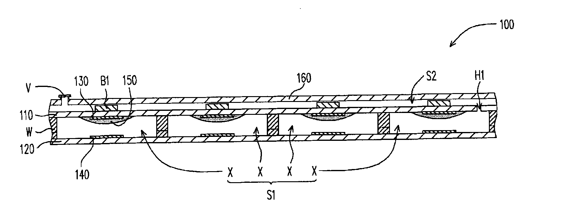
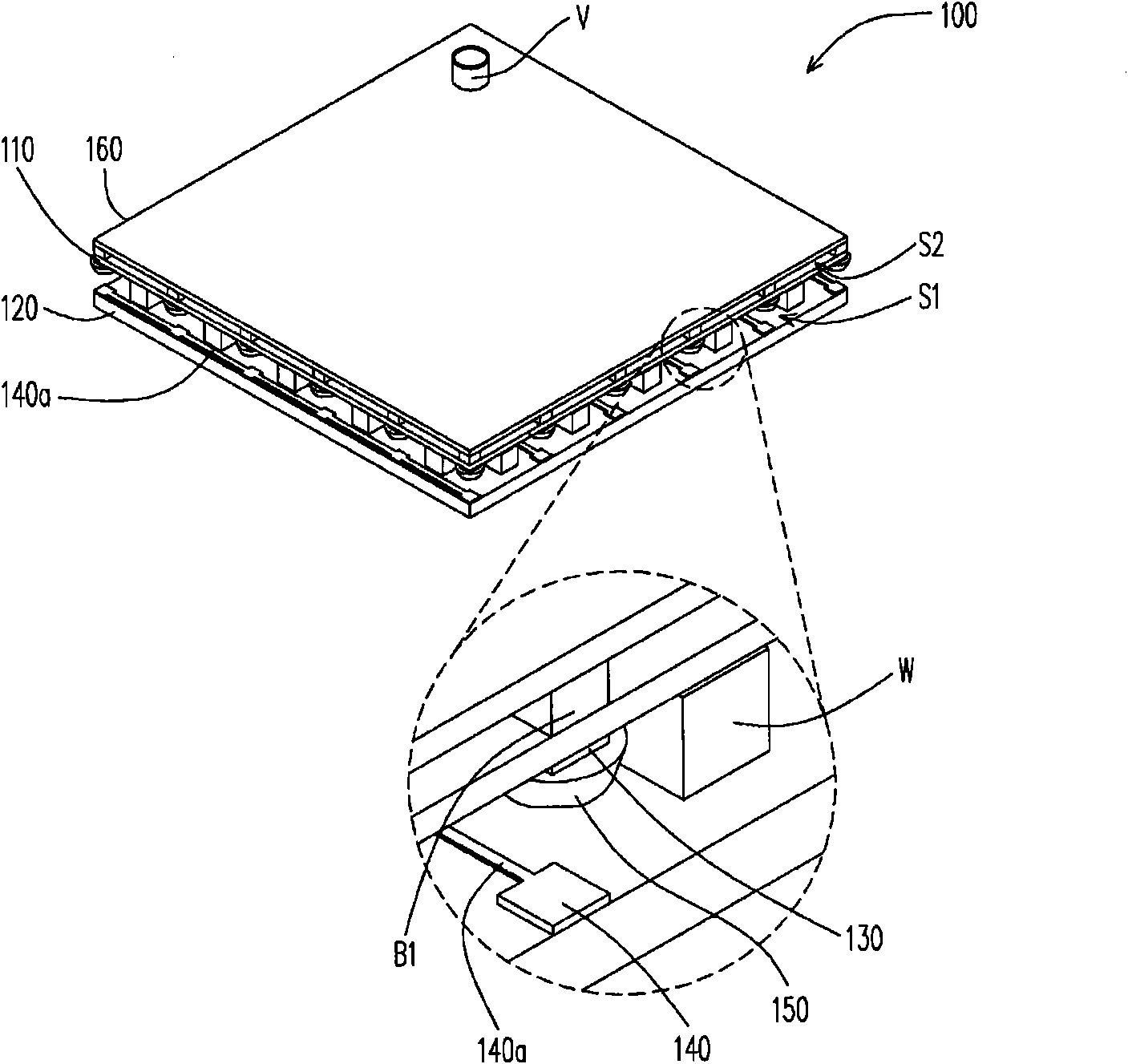
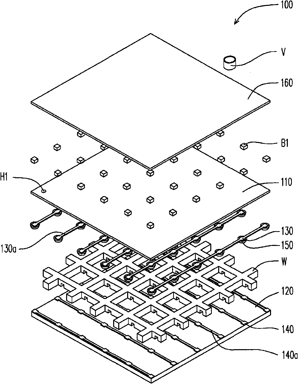
[0046] Figure 1A is a schematic cross-sectional view of a flexible electronic pressure sensing device according to an embodiment of the present invention, Figure 1B for Figure 1A A perspective view of the flexible electronic pressure sensing device, Figure 1C for Figure 1A An exploded perspective view of a flexible electronic pressure sensing device. Please also refer to Figure 1A , Figure 1B and Figure 1C , the flexible electronic pressure sensing device 100 of this embodiment includes a first flexible film 110, a second flexible film 120, a plurality of first electrodes 130, a plurality of second electrodes 140, a plurality of first sensing blocks 150, a third The flexible film 160 and a plurality of first bumps B1.

[0047] The second flexible film 120 is disposed below the first flexible film 110 at intervals, and forms a first space S1 with the first flexible film 110 . The first electrodes 130 are arranged in an array on the first flexible film 110 and locate...


PUM


Abstract

The invention relates to a flexible electronic pressure sensing device capable of sensing a large area and being manufactured at low cost and a manufacturing method thereof. The device comprises multiple layers of flexible films, a plurality of electrodes, a plurality of sensing blocks and a plurality of bumps, wherein the flexible films are arranged at intervals to define two spaces; the electrodes and the sensing blocks are arranged on the flexible films and positioned in one space; and the bumps are arranged on the flexible films and positioned in the other space. The air in the spaces maintains a relative distance between two flexible films which are provided with the electrodes and the sensing blocks. In case of deformation, the flexible electronic pressure sensing device can avoid error sensing signals caused by the mutual contact of the sensing block and the electrode or two sensing blocks respectively arranged on different flexible films. In addition, the invention also relates to the method for manufacturing the flexible electronic pressure sensing device.

Description

technical field [0001] The present invention relates to a flexible electronic pressure sensing device and a manufacturing method thereof, more particularly, the present invention relates to a flexible electronic pressure sensing device applicable to large-area sensing and low-cost manufacturing and a manufacturing method thereof. Background technique [0002] Flexible electronics generally refers to the technology and application of making functional sensing materials on flexible or bendable substrates. Currently, there are plastic electronics (Plastic electronics), printed electronics (Printed Electronics), organic electronics (Organic Electronics) and polymer electronics (Polymer electronics) and other new technologies, and these technologies have been applied to the design and production of flexible sensors. The advantages of this technology are the use of printing technology, and it is suitable for large-area sensing and low-cost production. [0003] Most of the general ...

Claims


Application Information

Patent Timeline
Patent Type & Authority Applications(China)
IPC IPC(8): G01L1/20G01L1/18G01L1/16G01L1/14G01L1/12
Inventor 张文阳林恒如沈煜棠
Owner IND TECH RES INST
Learn More