


Quick Research
Generate reliable direction feasibility study reports for your R&D in just a few steps.

Technical Q&A
Discover and master advanced knowledge NOW. Basics, ideas, possibilities, all at once.

Find Solutions
As an expert in R&D theories, this can generate solutions to your technical problems instantly.

Evaluate Feasibility
Analyze your overall solution with one click, know your potential R&D risks in advance.

Monitor Landscape
Get weekly tech updates, stay abreast of the latest tech innovations and key insights.
Heat exchanger
A heat exchanger and heat pipe technology, applied in evaporator/condenser, lighting and heating equipment, refrigeration components, etc., can solve the problem of reduced heat exchange efficiency of heat exchanger, poor heat exchange effect, and insufficient heat exchange in micro-channels and other problems to achieve the effect of balanced heat exchange effect
- Summary
- Abstract
- Description
- Claims
- Application Information
AI Technical Summary
Problems solved by technology
Method used
Image

Examples
no. 1 approach
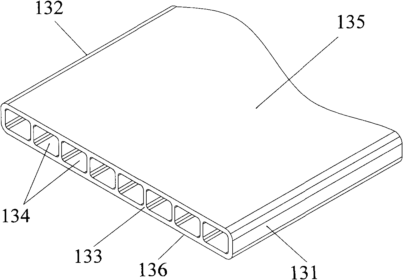
[0034] Please refer to Figure 4 , Figure 4 It is a perspective view of the heat dissipation pipe according to the first embodiment of the present invention.
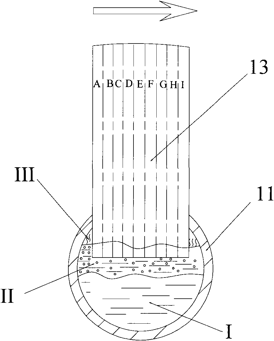
[0035]In the first embodiment, the heat dissipation pipe 13 provided by the present invention has two side edges 131 and 132 , and the two side edges 131 and 132 are arranged parallel to each other. The radiating pipe also includes an upper plane 135 and a lower plane 136 that are parallel to each other; the two side edges 131 and 132 and the upper planes 135 and 136 enclose a flat radiating pipe 13 . There are several microchannels 134 inside the heat dissipation pipe 13, and the number of the microchannels can be determined according to actual needs. In the present invention, in order to facilitate the description of the process of the refrigerant entering the microchannels, in this embodiment, the number of the microchannels is set to 7, and each specific microchannel is represented by the symbols A-G respectively...
no. 2 approach
[0046] Please refer to Image 6 , Image 6 It is a perspective view of the heat dissipation pipe according to the second embodiment of the present invention.
[0047] In the second embodiment, the heat dissipation pipe 13 provided by the present invention has two side edges 131 and 132 , and the two side edges 131 and 132 are arranged parallel to each other. The radiating pipe also includes an upper plane 135 and a lower plane 136 that are parallel to each other; the two side edges 131 and 132 and the upper planes 135 and 136 enclose a flat radiating pipe 13 . There are several microchannels 134 inside the heat dissipation pipe 13, and the number of the microchannels can be determined according to actual needs. In the present invention, in order to facilitate the description of the process of the refrigerant entering the microchannels, in this embodiment, the number of the microchannels is set to 7, and each specific microchannel is represented by the symbols A-G respectivel...
PUM
 Abstract
Description
Claims
Application Information
 - R&D Engineer
- R&D Manager
- IP Professional
- Industry Leading Data Capabilities
- Powerful AI technology
- Patent DNA Extraction
Browse by: Latest US Patents, China's latest patents, Technical Efficacy Thesaurus, Application Domain, Technology Topic, Popular Technical Reports.
© 2024 PatSnap. All rights reserved.Legal|Privacy policy|Modern Slavery Act Transparency Statement|Sitemap|About US| Contact US: help@patsnap.com