
Method for reducing vibration or bending deformation of spindle rotor in high-speed electric spindle

A high-speed electric spindle and spindle rotor technology, applied in the field of mechanical vibration, can solve the problems of unreleased vibration bending deformation, increased spindle bending deformation, increased bearing load, etc., to reduce stress, improve life, and simple structure. Effect

Inactive Publication Date: 2010-07-14
LUOYANG BEARING RES INST CO LTD
View PDF0 Cites 7 Cited by
  • Summary
  • Abstract
  • Description
  • Claims
  • Application Information

AI Technical Summary

Problems solved by technology

Since the main shaft rotor and the sleeve are only connected by bearings and there is no shock absorber, the two ends of the main shaft rotor are rigidly constrained by the bearings and the sleeve, so that the vibration and bending deformation generated when the electric spindle rotates at high speed can hardly be released, resulting in The bending deformation of the main shaft increases, the bearing load increases, and the vibration increases

Method used


Image

  • Method for reducing vibration or bending deformation of spindle rotor in high-speed electric spindle
  • Method for reducing vibration or bending deformation of spindle rotor in high-speed electric spindle
  • Method for reducing vibration or bending deformation of spindle rotor in high-speed electric spindle

Examples


Embodiment Construction

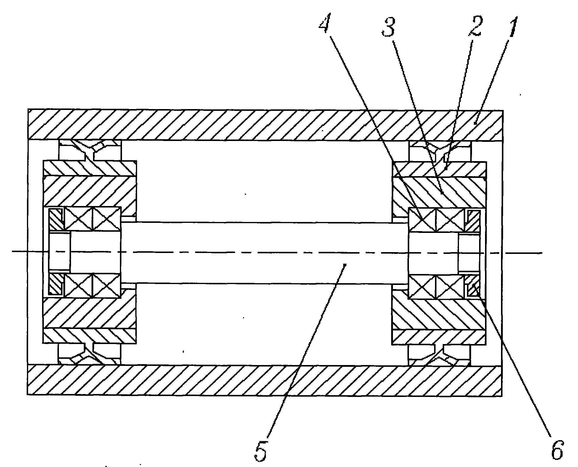
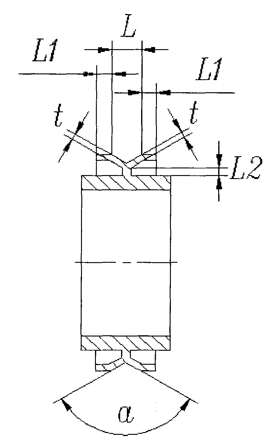
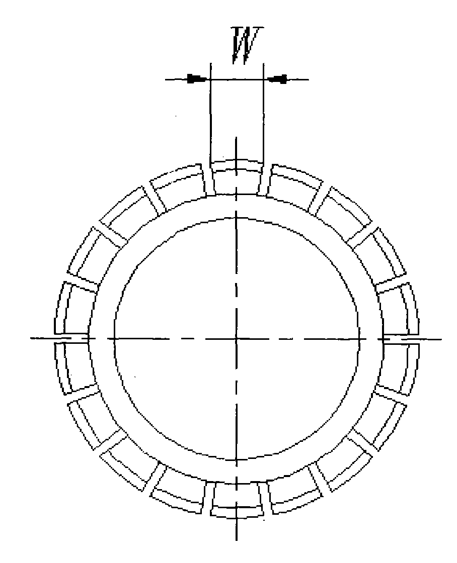
[0020] to combine figure 1 , the method for reducing the vibration or bending deformation of the main shaft rotor in the high-speed electric spindle of the present invention is to arrange shock absorbing devices with the same structure at the supporting points at both ends of the main shaft rotor 5, the shock absorbing devices include an elastic support ring 2 and a bearing seat 3. Bearings 4 are first installed on the supporting points at both ends of the main shaft rotor 5 and fastened by nuts 6, and then a bearing seat 3 is arranged on the outer diameter of the bearing. The axial width of the bearing seat is ≥ bearing width + nut width + bearing seat rib width , and finally fit the elastic support ring 2 tightly on the outer diameter of the bearing seat, the total width of the elastic support ring = the axial width of the bearing seat, Y-shaped warping wings with equal intervals are arranged radially on the inner cylinder of the elastic support ring, and the The main shaft ...


PUM


Abstract

The invention relates to a method for reducing vibration or bending deformation of a spindle rotor in a high-speed electric spindle. Supporting points at two ends of the spindle rotor (5) are respectively provided with an elastic supporting ring (2) and a bearing seat (3), which have the same structures; when impact load which is triggered by vibration generated by high-speed rotation of the spindle rotor is transmitted to the elastic supporting ring through a bearing (4) and the bearing seat, and an Y-shaped raised wing of the elastic supporting ring has elastic deformation which can absorb part of vibrating energy, so the impact load among the bearing, the bearing seat and a sleeve (1) is lightened; as the Y-shaped raised wing of the elastic supporting ring has elasticity, rigid restriction borne by the supporting points at the two ends of the spindle rotor is weakened; therefore, the vibration or the bending deformation of the spindle rotor is effectively released; the self-centering effect of high-speed rotation of the spindle rotor is enhanced; and the method effectively prevents the bending deformation of the spindle rotor, reduces the force borne by the bearing, and improves the service life of the high-speed electric spindle.

Description

technical field [0001] The invention belongs to the technical field of mechanical vibration, and in particular relates to a method for reducing vibration or bending deformation of a main shaft rotor in a high-speed electric main shaft. Background technique [0002] The structure of the high-speed electric spindle is similar to that of a motor, but its function is essentially different from that of a motor. The sleeve of the high-speed electric spindle is similar to the base of the motor, the spindle rotor of the high-speed electric spindle is similar to the rotor of the motor, and the spindle rotor is installed in the sleeve through the bearing. The overall structure of the high-speed electric spindle is relatively compact, its speed is usually higher than that of the motor, the spindle rotor rotates smoothly, and the spindle rotor generally has some specific functions and not only for transmission purposes. [0003] With the advancement of science and technology, the indus...

Claims


Application Information

Patent Timeline
IPC IPC(8): F16F15/04
Inventor 肖汝锋陈长江
Owner LUOYANG BEARING RES INST CO LTD
Learn More