Electrically operated valve

An electric valve, valve chamber technology, applied in the direction of lift valve, valve details, valve device, etc., can solve the problems of cumbersome process, failure, stress concentration, etc.

Active Publication Date: 2010-07-07
ZHEJIANG SANHUA INTELLIGENT CONTROLS CO LTD
View PDF4 Cites 9 Cited by
  • Summary
  • Abstract
  • Description
  • Claims
  • Application Information

AI Technical Summary

Problems solved by technology

[0022] Therefore, in Patent Document 6, in order to fix the guide support body on the airtight cover, the airtight cover must be machined to form the convex portion, and therefore, there is a problem that the process is cumbersome when performing the machining. problems, and there may be stress concentration phenomenon after the outer cover is machined, and it may rupture under pulse pressure, resulting in product failure

Method used


Image

  • Electrically operated valve
  • Electrically operated valve
  • Electrically operated valve

Examples


Embodiment Construction

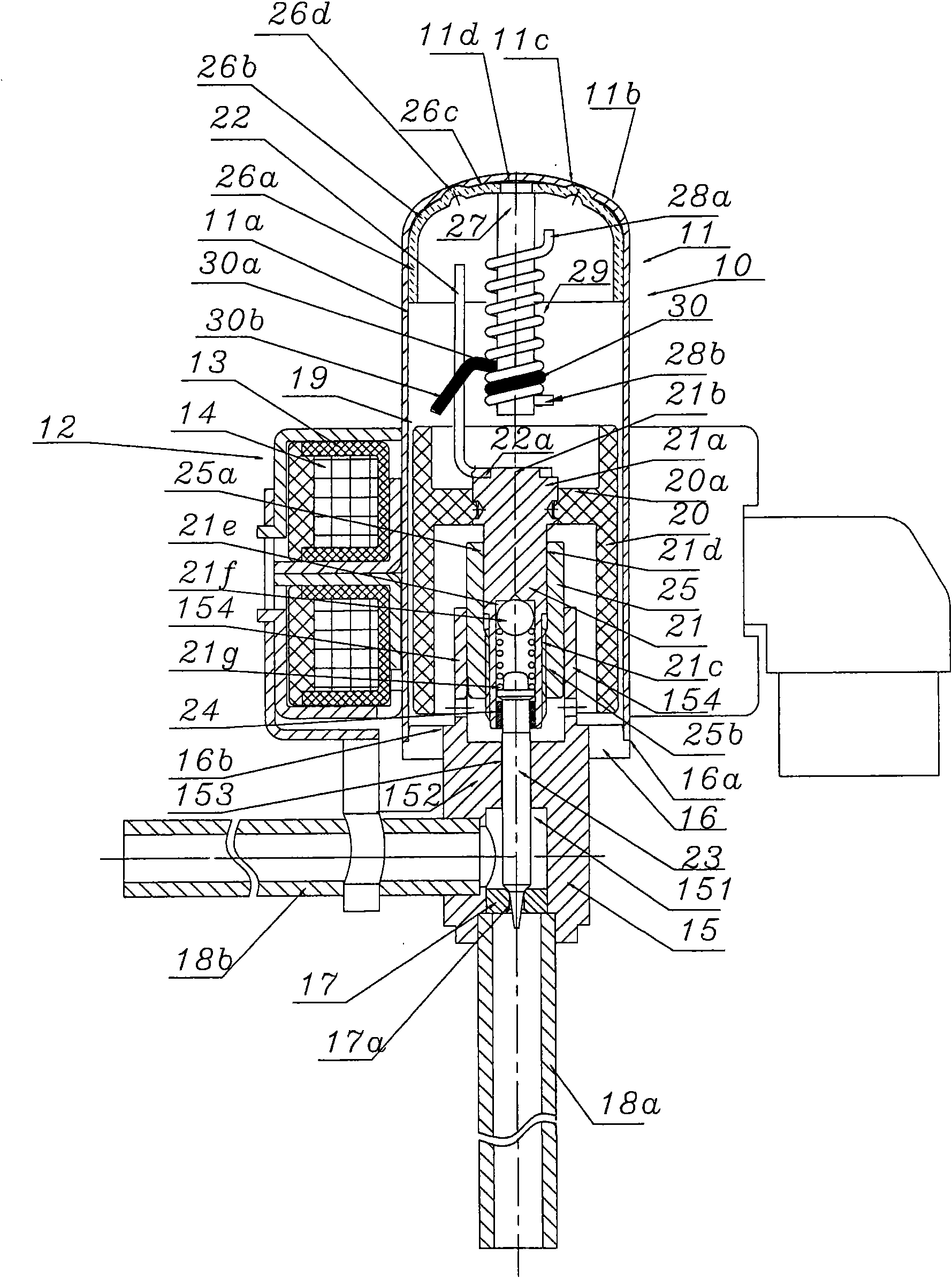
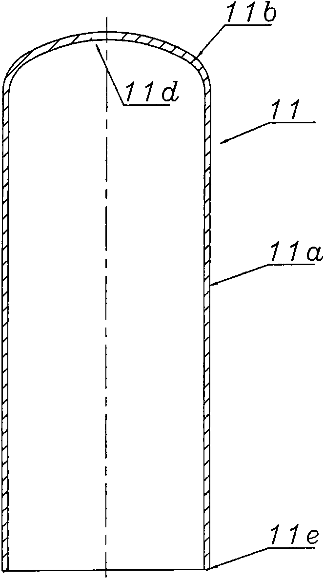
[0069] Below, refer to Figure 1A , Figure 1B , Figure 1C , Figure 1D , Figure 1E as well as Figure 1F A specific embodiment of the electric valve of the present invention will be described.

[0070] Figure 1A It is an overall structural diagram of an electric valve related to a specific embodiment of the present invention. Figure 1A The electric valve indicated by reference numeral 10 in its entirety has a cylindrical airtight housing 11 made of a stamped metal such as stainless steel, and a stator portion 12 disposed on the outer periphery of the housing 11 . The stator part 12 has a coil 14 arranged in the stator yoke 13, and since the electric valve with this configuration is basically the same as the conventional electric valve, detailed description thereof will be omitted. Therefore, only for Figure 1A The differences between the illustrated embodiment and the conventional electric valve, that is, the airtight housing 11 and the stopper mechanism provided on ...


PUM


Abstract

An electrically operated valve comprises a sealed housing in which the bottom is fixed on a valve body provided with a valve chamber and a throttling hole; a step motor installed inside the sealed housing comprises a stator coil and an rotor in opposite configuration; a valve needle approaches to or leaves away from the throttling hole according to the driving of the step motor; the inner part of the sealed housing is provided with a stop mechanism for stopping the rotation of the rotor; the stopping mechanism limits the up and down movement of the valve needle so as to control the flow rate of the fluid passing in and out of the valve chamber; the sealed housing comprises a cylindrical wall part, a bent part, an arc part, and a cover-shaped shield component; the cover-shaped shield component comprises a short cylindrical wall part formed on the inner periphery surface of the head part connected through spot welding on the arc part; the cover-shaped shield component comprises a bent part and a top part which are integrally formed; the short cylindrical wall part, the bent part and the top part are respectively formed into the external periphery shapes of the short cylindrical wall part, the bent part, and the top part along the sealed housing; and simultaneously, the cover-shaped shield component is provided with the stop mechanism.

Description

technical field [0001] The invention relates to an electric valve, in particular to a valve suitable for carbon dioxide (CO 2 ) and other natural refrigerants in the refrigeration cycle to control the flow of refrigerant electric valve. Background technique [0002] In the refrigeration cycle, an electric valve used as a flow control valve includes a valve body, a valve core or a valve needle that is close to or away from a valve seat formed on the valve body, and a cylindrical casing (closed) fixed on the valve body. Type outer cover), and the rotor that is arranged in this outer cover, and the stator that is arranged on the outside of described airtight type outer cover and its rotor opposite configuration; Described rotor and stator constitute stepping motor, moreover, the Inside, there is a stop mechanism as a rotation stop mechanism of the rotor, and the stop mechanism limits the rotation range of the rotor and stops the vertical movement of the valve needle. [0003]...

Claims


Application Information

Patent Timeline
Patent Type & Authority Applications(China)
IPC IPC(8): F16K1/38F16K31/04F16K27/00F25B41/04
Inventor 詹才意魏先让
Owner ZHEJIANG SANHUA INTELLIGENT CONTROLS CO LTD
Why Eureka
Try Eureka