Methods, systems and/or apparatus relating to inducers for turbine engines

A deflector, maximum flow technology, used in turbine/propulsion cooling, engine cooling, engine components, etc., to solve problems such as impossible

Active Publication Date: 2010-07-07
GENERAL ELECTRIC TECH GMBH
View PDF6 Cites 2 Cited by
  • Summary
  • Abstract
  • Description
  • Claims
  • Application Information

AI Technical Summary

Problems solved by technology

However, conventional deflector designs that include a cylindrical region extending from the throat to the trailing edge make such improvements substantially impossible without distorting or damaging the optimal geometry of the trailing edge

Method used


Image

  • Methods, systems and/or apparatus relating to inducers for turbine engines
  • Methods, systems and/or apparatus relating to inducers for turbine engines
  • Methods, systems and/or apparatus relating to inducers for turbine engines

Examples


Embodiment Construction

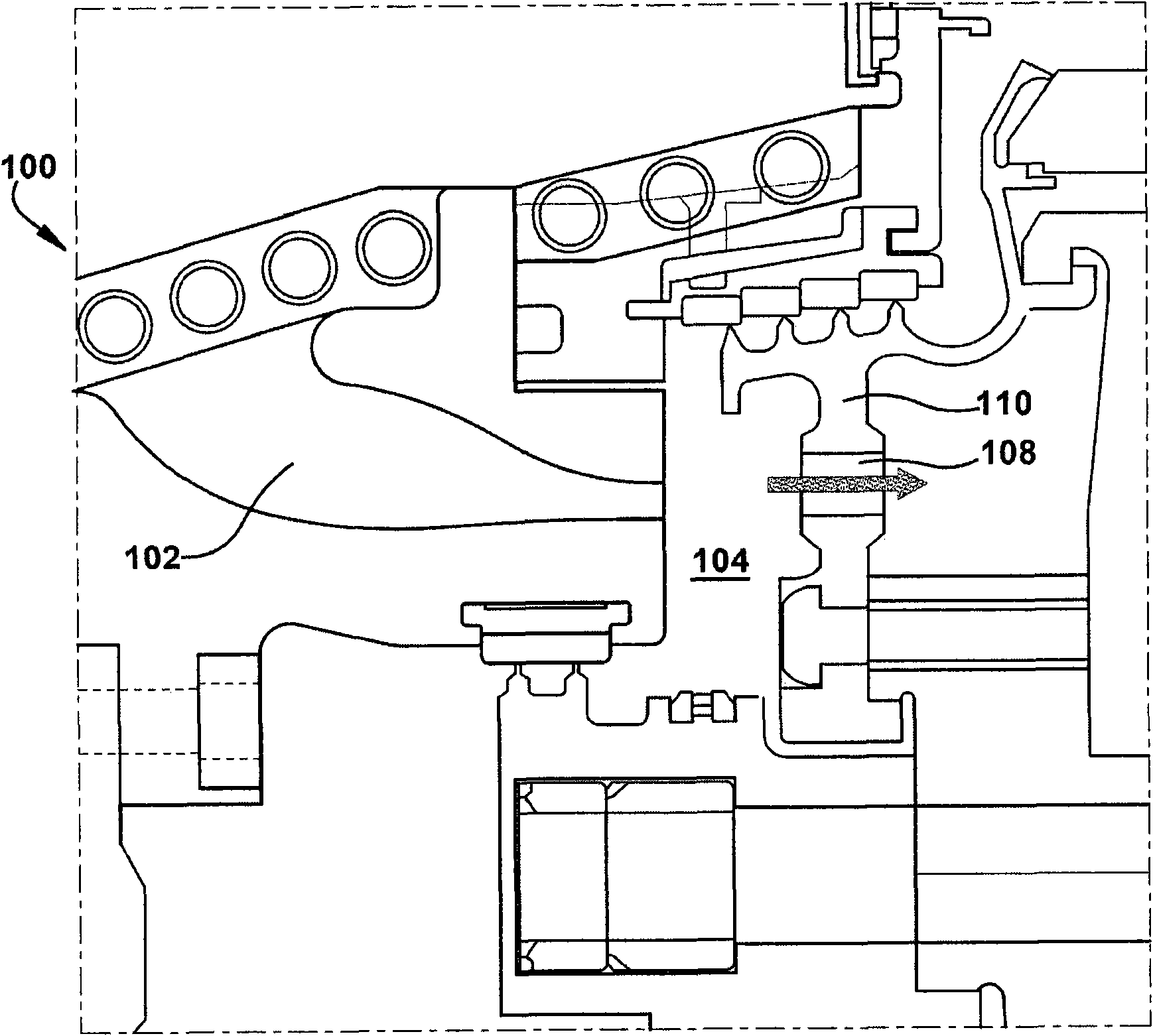
[0015] Referring now to the attached picture, figure 1 A schematic diagram of a section of gas turbine engine 100 is shown. In general, gas turbine engines operate by extracting energy from a pressurized hot gas stream produced by burning fuel in a compressed air stream. Gas turbine engines are typically constructed with an axial compressor mechanically coupled to a downstream turbine section or turbine by a common shaft or rotor and a combustor positioned between the compressor and turbine. Note that the invention below can be used in all types of turbine engines, including gas turbine engines, steam turbine engines, and aero engines, among others. In the following, the invention will be described in relation to a gas turbine engine. This description is exemplary only, and is not intended to be limiting in any way.

[0016] Compressors typically include multiple axially stacked stages. Each stage may include a row of compressor rotor blades followed by a row of compressor...


PUM


Abstract

The invention relates to methods, systems and / or apparatus relating to inducers for turbine engines. An inducer (140) that includes a profiled throat (144). In some embodiments, the inducer (140) includes a conical shape upstream of the profiled throat (144) with a relatively large circular inlet (142) that narrows to the profiled throat (144) and, downstream of the profiled throat (144), a downstream section that broadens from the profiled throat (144). The profiled throat (144) may include an approximate convergent-divergent nozzle geometry.

Description

technical field [0001] This application generally relates to methods, systems and / or apparatus for improving the efficiency and / or operation of turbine engines, as used herein and unless specifically indicated otherwise, this is meant to include all types of turbine engines or rotary engines, including Gas turbine engine, aero engine, steam turbine engine, etc. More specifically, but not by way of limitation, the present application relates to methods, systems and / or apparatus relating to improved inducer designs for turbine engines. Background technique [0002] Gas turbine engines typically include a cooling system that provides cooling air to turbine rotor components (eg, turbine blades) in order to limit the temperatures experienced by such components. Prior art cooling systems typically take air from the engine's compressor to cool the turbine components, after which the air is diverted and then directed through an axial passage to the turbine section of the engine. A...

Claims


Application Information

Patent Timeline
Patent Type & Authority Applications(China)
IPC IPC(8): F02C7/12
CPCF01D5/081Y02T50/673Y02T50/676F05D2260/97F05D2260/14F01D5/082Y02T50/60F02C7/18F05D2220/32F05D2260/20
Inventor A·哈特曼
Owner GENERAL ELECTRIC TECH GMBH
Why Eureka
Try Eureka