
Rotary piston cylinder

A technology of rotating pistons and cylinders, applied in the field of piston cylinders, can solve the problems of low energy conversion efficiency, high sealing difficulty, low power frequency, etc., and achieve the effects of excellent clutch braking performance, wide torque output range and wide power range.

Inactive Publication Date: 2010-07-07
周华
View PDF0 Cites 4 Cited by
  • Summary
  • Abstract
  • Description
  • Claims
  • Application Information

AI Technical Summary

Problems solved by technology

[0003] Crankshaft-connecting-rod-piston mechanism, its structural feature is that the energy conversion is realized by the positive (reverse) conversion of linear reciprocating motion and rotary motion, the main disadvantages are non-uniform speed, non-equal torque, discontinuous power output, inertial impact, dead As a result, related machines need multi-level wrong-phase linkage, large vibration, high noise, low efficiency, low frequency of work, complex structure, and high processing difficulty
[0004] The turbine mechanism is characterized by the conversion process of fluid kinetic energy in the middle of the positive (reverse) conversion process of fluid pressure energy and mechanical energy. Its main disadvantages are large conversion loss, low efficiency, large volume, high material requirements, and difficult processing. High, low life
[0005] The vane motor mechanism is characterized by eccentric rotation. The main disadvantages are non-constant speed, non-constant torque, non-continuous power output, difficult sealing, low output power, low efficiency, high noise, and easy vibration.
[0006] In other non-mainstream rotary motion mechanisms, there are basically local defects in the above mechanisms. The most important point is that the energy conversion efficiency is low, and the non-continuous stable output

Method used


Image

  • Rotary piston cylinder
  • Rotary piston cylinder
  • Rotary piston cylinder

Examples


Embodiment 1

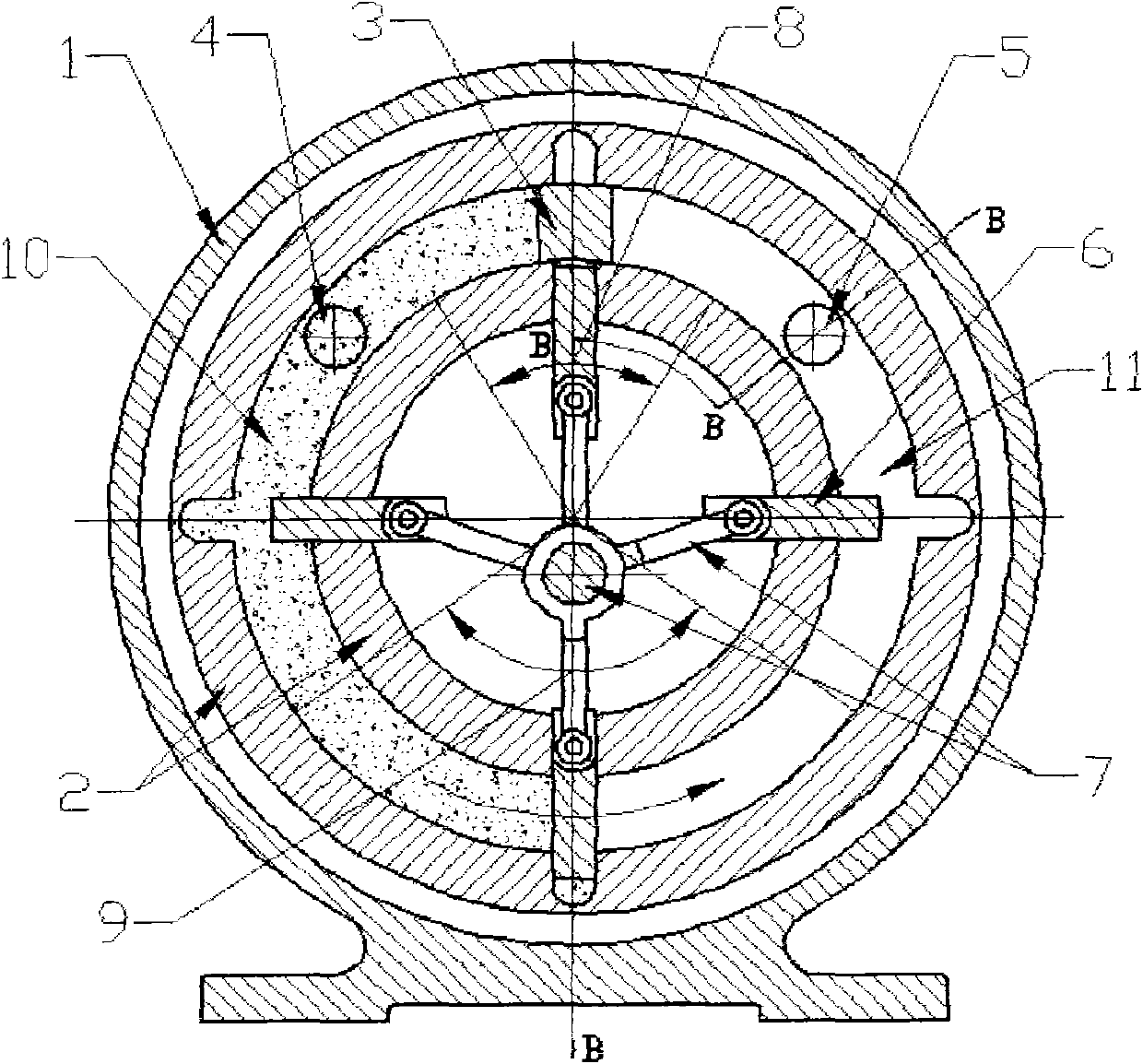
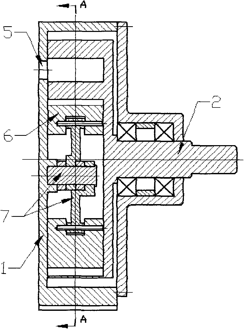
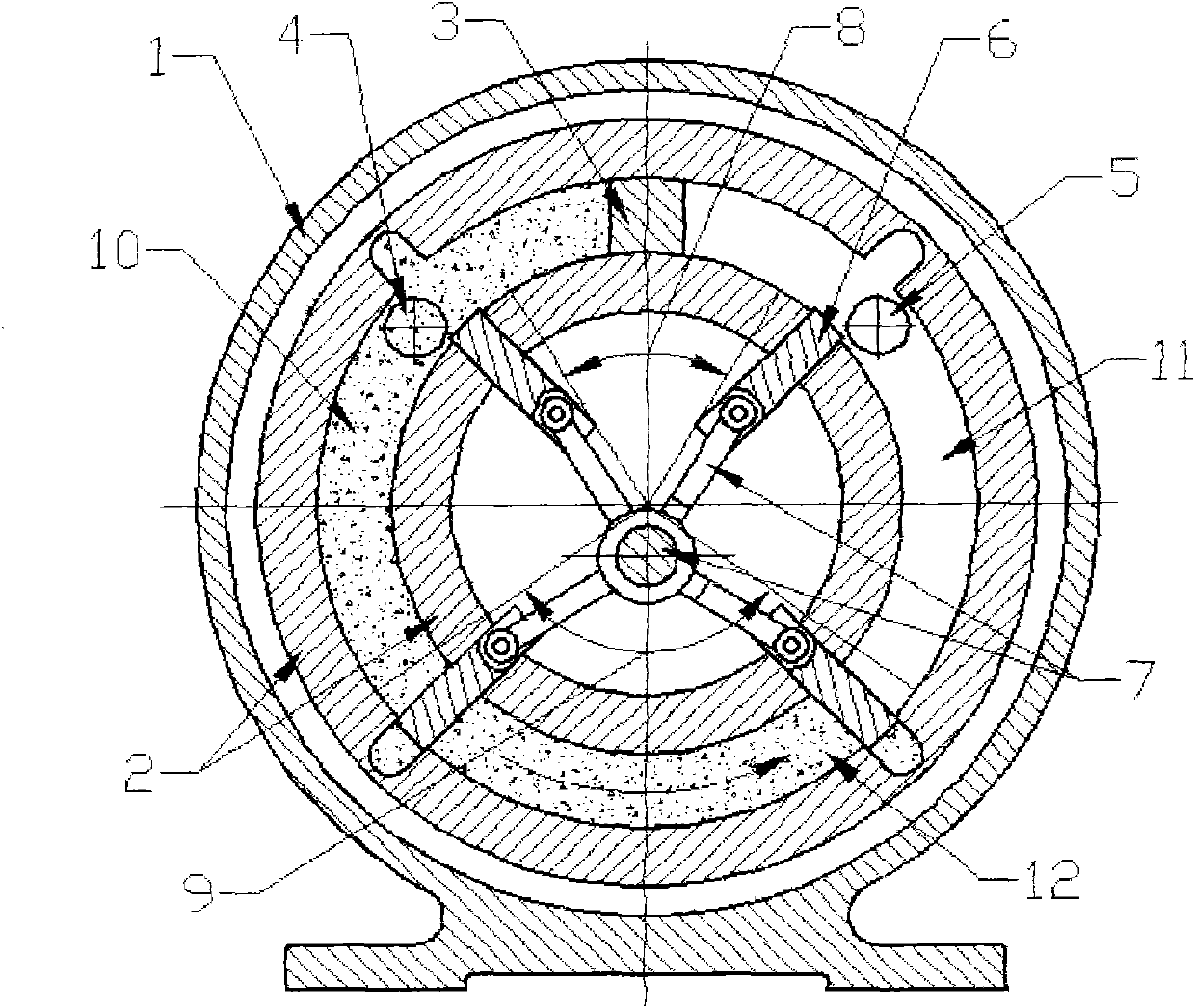
[0022] Such as figure 1 figure 2 As shown, because when the rotary piston 6 is outside the packing angle 9, the radial pressure will generate reaction torque through the crankshaft linkage mechanism 7, which will cause fluctuations in the output, and increase the normal effective bearing area and radial area of ​​the rotary piston 6 Increasing the ratio of the connecting rod length to the eccentricity will reduce the magnitude of this effect; increasing the number of rotary pistons 6 can reduce the eccentricity and the size of the body, but more than 3 will increase the magnitude of the fluctuation and the difficulty of processing And cost, so the number of rotary piston 6 is advisable with 3 or 4.

[0023] Rotary ring 6 is set in a sheet shape, with small radial anti-torque, stable output, and large load-carrying capacity; however, the ease of processing, sealing and lubricity are slightly worse than those of the columnar shape.

[0024] The partition plate 3, the working ...


PUM


Abstract

The invention discloses a rotary piston cylinder, which is a mechanism capable of positively / reversely converting fluid pressure energy and mechanical energy in a one-way continuous circular motion mode. The rotary piston cylinder mainly comprises a cylinder body (1), a rotor (2), a clapboard (3), a working medium inlet (4), a working medium outlet (5), a rotary piston (6) and a crankshaft connecting rod mechanism (7). The working principle of the rotary piston cylinder is the same as that of a vane type oscillating cylinder. The rotary piston cylinder is characterized in that: the working rotary piston (6) displaces on a plane which is parallel to the axis under the action of the crankshaft connecting rod mechanism (7), and can cross the clapboard (3) to apply work circularly and realize the one-way continuous circular motion mode. The rotary piston cylinder has the characteristics of high energy conversion efficiency, high bearing capacity, widely permitted working media, continuous and stable output, cascade connection capacity, load-carrying self-start, stepless speed change, high-speed response, fast reversing, overload protection, excellent clutch brake performance, and the like.

Description

1. Technical field: [0001] The invention relates to a piston cylinder, whose movement mode is continuous circular rotation, a mechanism capable of positively (reversely) converting fluid pressure energy and mechanical energy, and a new type of fluid power and actuator, which can be applied to pumps and compressors , motors, clutches, brakes, continuously variable transmissions, hydraulic turbines, gas turbines, internal combustion engines and other fields. 2. Background technology: [0002] At present, there are mainly crankshaft connecting rod piston mechanism, turbine mechanism and vane motor mechanism that are relatively mature in the forward (reverse) conversion of fluid pressure energy and mechanical energy in the form of continuous circular rotation. [0003] Crankshaft-connecting-rod-piston mechanism, its structural feature is that the energy conversion is realized by the positive (reverse) conversion of linear reciprocating motion and rotary motion, the main disadvan...

Claims


Application Information

Patent Timeline
Patent Type & Authority Applications(China)
IPC IPC(8): F01C1/00
Inventor 周华
Owner 周华
Learn More