
Method of and device for connecting metal bands

一种金属带、夹紧装置的技术,应用在金属加工、金属轧制、金属轧制等方向,能够解决抗弯刚度剥裂等问题,达到减少强度的效果

Inactive Publication Date: 2010-07-07
BWG BERGWERK & WALZWERK MASCHINENBAU GMBH
View PDF3 Cites 10 Cited by
  • Summary
  • Abstract
  • Description
  • Claims
  • Application Information

AI Technical Summary

Problems solved by technology

With larger strip thicknesses there is the danger that the adhesive seam is torn off during the run around the rollers in the strip processing line due to the bending stiffness of the strip

Method used


Image

  • Method of and device for connecting metal bands
  • Method of and device for connecting metal bands
  • Method of and device for connecting metal bands

Examples


Embodiment Construction

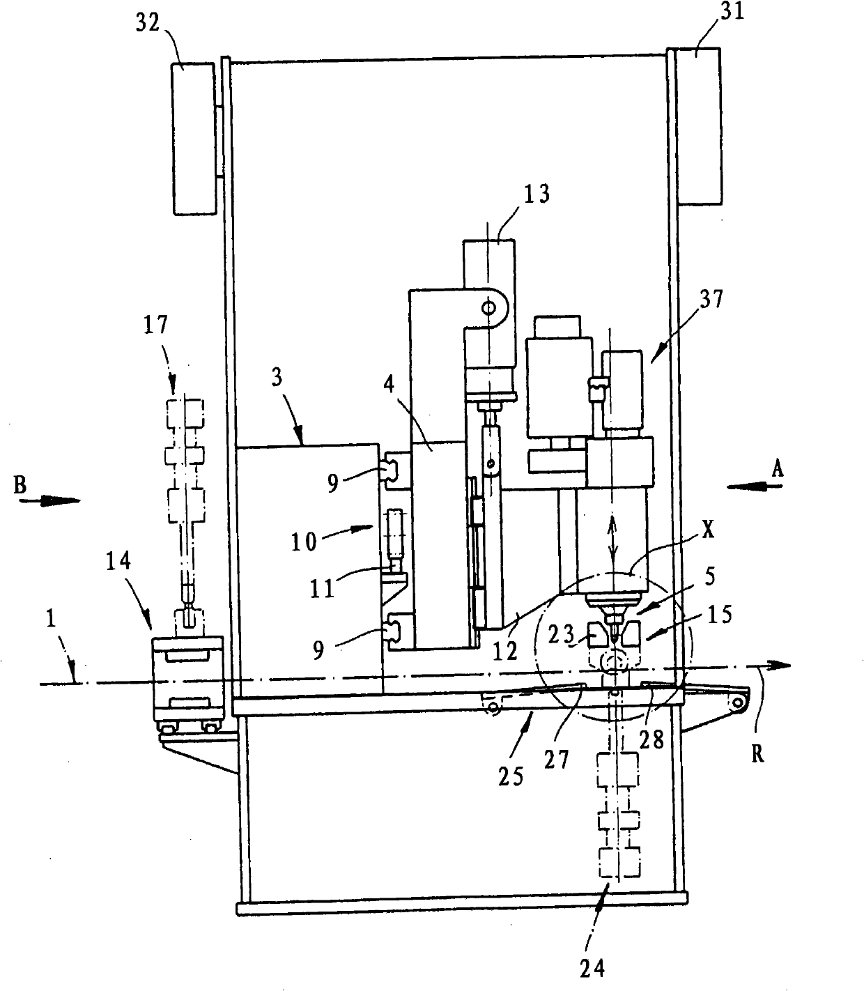
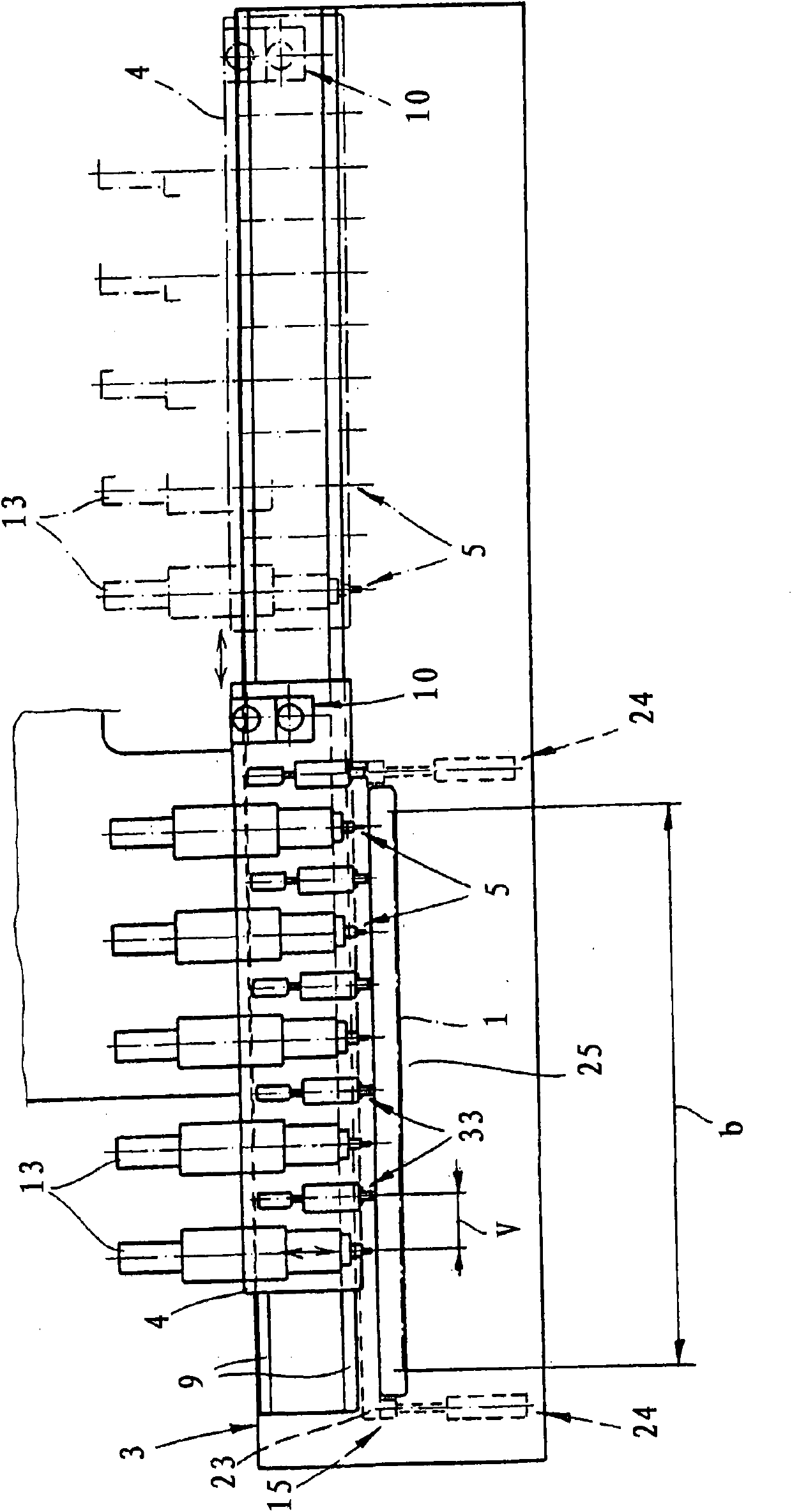
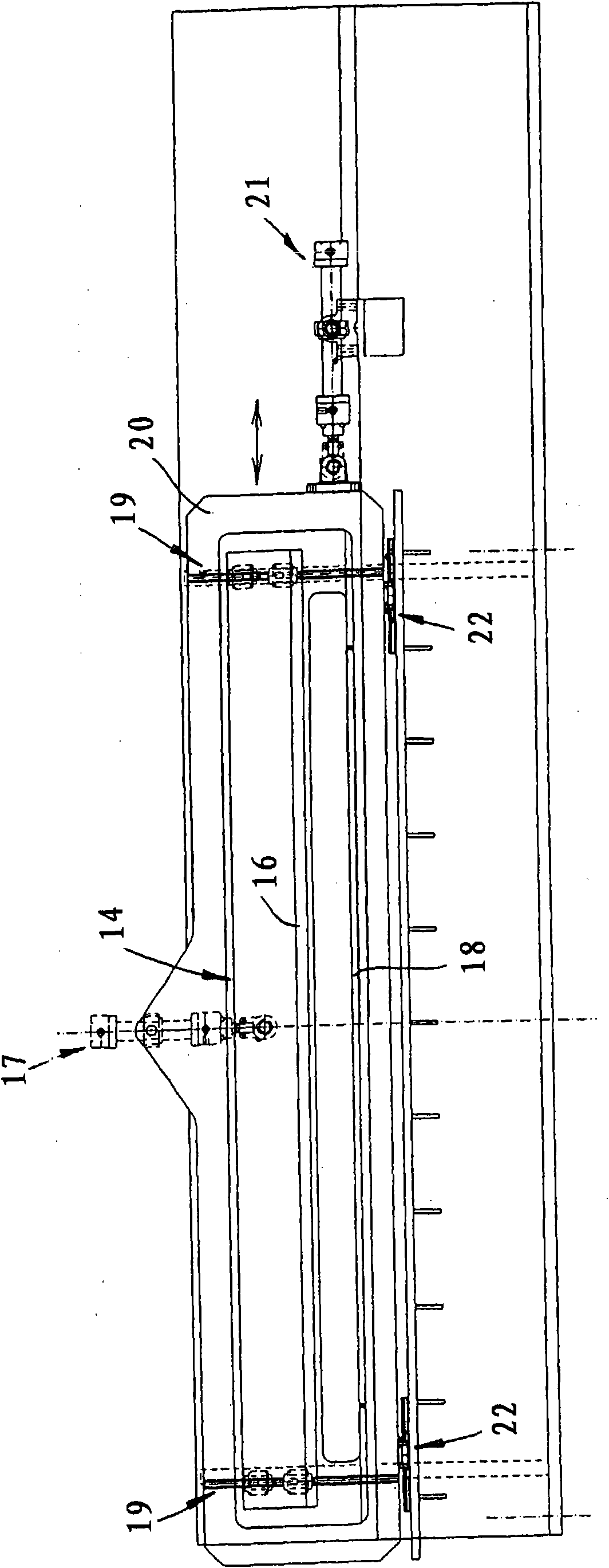
[0033] The figure shows a device for connecting a strip end 1 a of a first metal strip 1 and a strip start 2 a of a second metal strip 2 . Such a device is preferably integrated in an inlet area with a treatment device. In such strip processing plants (which are also referred to as strip processing lines), metal strips coiled into coils (coils) are unrolled in the entry area, then pass through different processing stations and are coiled up again in the exit area , or otherwise continue to be processed, such as being cut into metal blocks. The strip start 2a of a new strip is thus connected to the strip end 1a of the previous strip without having to constantly rethread the metal strip. Within the scope of the invention, this is achieved by welding, by positioning the strip end 1 a and the strip start 2 a one above the other with overlapping and welding to one another in the overlapping region at several welding points. During welding, the strip is in a rest position, ie the ...


PUM


Abstract

The invention especially relates to a method for connecting an end of a first metal strip to a beginning of a second metal strip in an inlet area of a strip treatment plant, comprises positioning the strip end and the strip beginning one upon the other under the formation of an overlap and then welding together in the area of the overlap at several welding points, where the welding points are setby friction point welding with a welding head.

Description

technical field [0001] The invention relates to a method and a device for connecting a strip end of a first metal strip to a strip start of a second metal strip, in particular in the entry area of ​​a strip processing plant, wherein the strip end and the The tape starts are positioned one above the other with an overlap and are welded to each other at a plurality of welding points in the region of the overlap. Background technique [0002] In a strip processing plant (it is also referred to as a strip processing line), metal strips, usually in coils (Coils), are unrolled in the entry area, then pass through one or more processing stations and, if necessary, in the exit area Rolled up, or optionally cut into pieces. In order that the straps do not have to be constantly rethreaded, the strap start of a new strap is connected to the strap end of the previous strap. It is known in practice to connect metal strips to one another by welding. [0003] Welding often causes proble...

Claims


Application Information

Patent Timeline
Patent Type & Authority Applications(China)
IPC IPC(8): B23K20/12B24B27/00
CPCB23K20/126B21C47/247B23K2201/16B23K20/1245B23K20/1265B21B15/0085B23K2203/10B23K2101/16B23K2103/10B23K20/12
Inventor A·诺埃D·鲍克洛F·阿姆鲍姆S·松塔格
Owner BWG BERGWERK & WALZWERK MASCHINENBAU GMBH
Learn More