Self-inductance DC (Direct Current) magnetic-dynamic method and device

A self-inductive, magnetic technology, applied in the direction of generators/motors, electrical components, etc., can solve the problems of complex structure and difficult control, and achieve the effect of high power utilization rate, easy control of operation, and large kinetic energy

Inactive Publication Date: 2010-06-30
邓金茂
View PDF1 Cites 0 Cited by
  • Summary
  • Abstract
  • Description
  • Claims
  • Application Information

AI Technical Summary

Problems solved by technology

[0002] The existing technology for converting magnetic energy into mechanical kinetic energy is as disclosed in the inventor’s patent application 200710092818.0. First, on the frame rotating along the rotating shaft, more than three permanent magnets with an odd number are evenly arranged along the periphery of the frame. block, and then move back and forth on the groove passing through the shaft center of the rack to attract the permanent magnet block, and drive the rack to rotate along the shaft by attracting the permanent magnet block. This structure is complex in structure due to the need to drive and attract the permanent magnet block. not easy to control

Method used


Image

  • Self-inductance DC (Direct Current) magnetic-dynamic method and device
  • Self-inductance DC (Direct Current) magnetic-dynamic method and device
  • Self-inductance DC (Direct Current) magnetic-dynamic method and device

Examples


Embodiment Construction

[0015] Now in conjunction with accompanying drawing and embodiment the present invention is described in further detail:

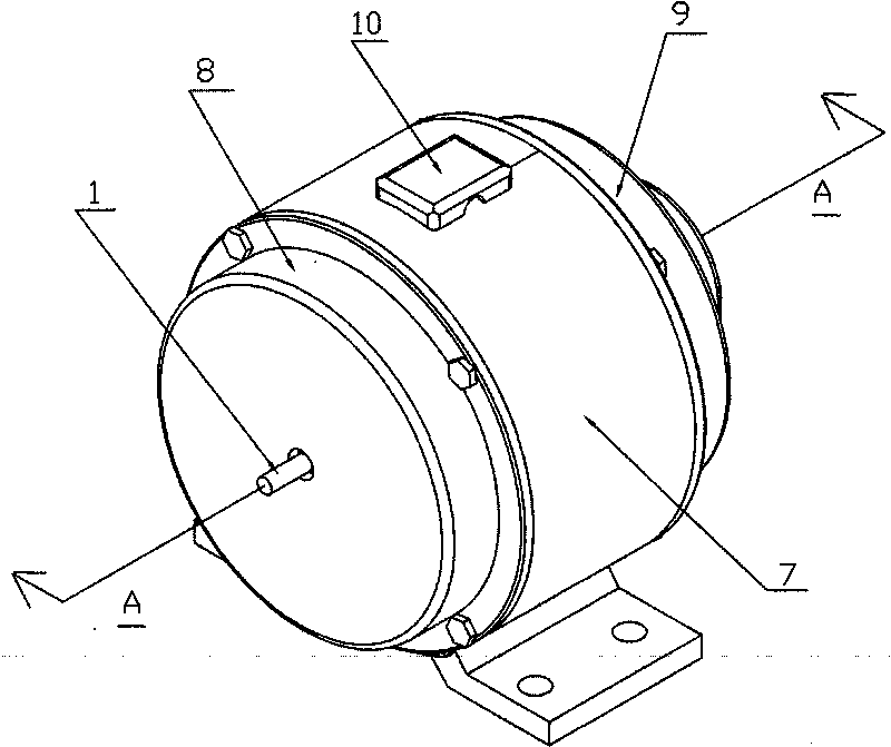
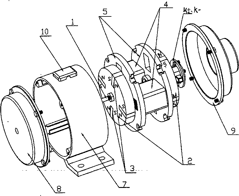
[0016] The self-inductive DC magnetic method of the present invention is realized in that on the rotor frame along the rotating shaft, more than two attracted permanent magnet blocks are evenly arranged along the periphery of the rotor frame, and the north and south poles of the attracted permanent magnet blocks are Located on the tangent of the circumference and the magnetic pole directions of all attracted permanent magnet blocks are the same, and more than one electromagnet is evenly arranged along the circumferential direction on the side of the rotor frame. The magnetic pole direction of the electromagnet is parallel to the axis of the rotating shaft. The positive power supply input terminal of the pole power supply input terminal is connected with the negative pole of the diode, the positive pole of the diode and the negative pole power supply input t...


PUM


Abstract

The invention relates to a self-induction DC magnetic-dynamic method and device. The method is characterized in that more than two attracted permanent magnet blocks are evenly arranged around a rotor support along a rotation shaft; the south and north poles of the attracted permanent magnet blocks are located on the tangents of the circumferences and the directions of the magnetic poles of all attracted permanent magnet blocks are the same; more than one electromagnet is evenly arranged along the direction of the circumference of the side surface of the rotor support; the directions of the magnetic poles of the electromagnets are parallel to the axes of the rotation shaft; the positive power input ends of the electromagnets are connected with the negative pole of a diode; and the positive pole of the diode and the negative power input ends of the electromagnets are connected with a power storage unit or a power consumption unit. Compared with the prior art, the invention has the advantages of simple structure, easy control of operation, high use ratio of electric energy, and large kinetic energy converted from permanent magnetic energy.

Description

Technical field: [0001] The invention relates to a magnetic method and device. Background technique: [0002] The existing technology for converting magnetic energy into mechanical kinetic energy is as disclosed in the inventor’s patent application 200710092818.0. First, on the frame rotating along the rotating shaft, more than three permanent magnets with an odd number are evenly arranged along the periphery of the frame. block, and then move back and forth on the groove passing through the shaft center of the rack to attract the permanent magnet block, and drive the rack to rotate along the shaft by attracting the permanent magnet block. This structure is complex in structure due to the need to drive and attract the permanent magnet block. Not easy to control. Invention content: [0003] The purpose of the present invention is to provide a self-inductance DC magnetic method and device with simple structure, easy control of operation and high utilization rate of electric...

Claims


Application Information

Patent Timeline
IPC IPC(8): H02N11/00
Inventor 邓金茂
Owner 邓金茂
Why Eureka
Try Eureka