
Method for controlling end-expiratory pressure and ventilator using same

An air pressure control and end-expiratory technology, applied in respirator and other directions, can solve the problems of inability to accurately control the patient's end-expiratory air pressure, jitter, difficult to maintain PEEP, etc., to avoid abnormal air pressure control, ensure smooth breathing, and ensure safety Effect

Inactive Publication Date: 2010-06-30
BEIJING AEONMED
View PDF3 Cites 17 Cited by
  • Summary
  • Abstract
  • Description
  • Claims
  • Application Information

AI Technical Summary

Problems solved by technology

[0004] For the control of PEEP of electric electronically controlled ventilator, PEEP is difficult to maintain due to the lack of continuous airflow
At present, some electric ventilators use a built-in micro air pump to provide continuous airflow for PEEP control, which obviously increases the cost and complexity; method, because the mechanical control diaphragm is not easy to maintain balance, it is easy to cause end-expiratory vibration, and the effect of accurately controlling the patient's end-expiratory pressure cannot be achieved

Method used

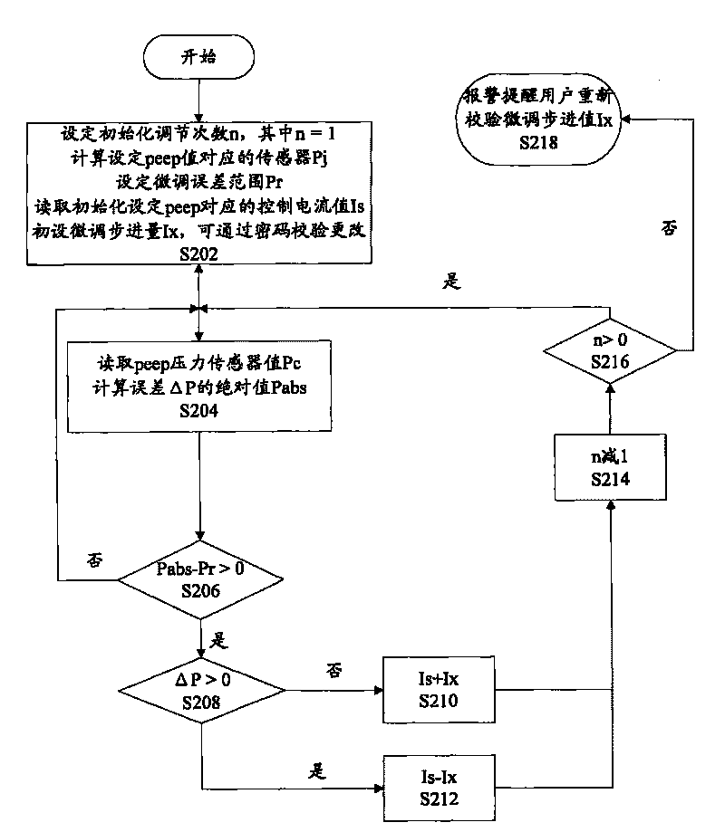
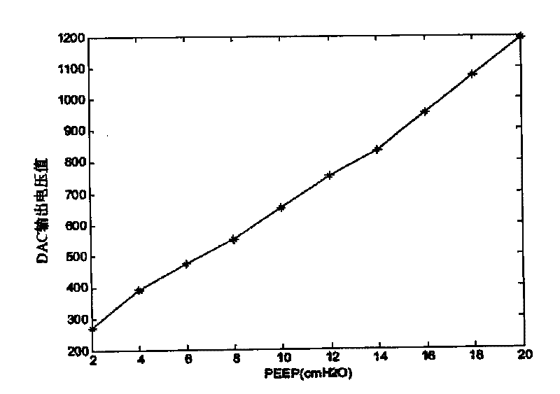

Image

  • Method for controlling end-expiratory pressure and ventilator using same
  • Method for controlling end-expiratory pressure and ventilator using same
  • Method for controlling end-expiratory pressure and ventilator using same

Examples


Embodiment Construction

[0017] The specific implementation manners of the present invention will be described in detail below with reference to the accompanying drawings.

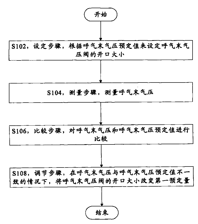
[0018] figure 1 is a flowchart of a method for controlling end-expiratory pressure according to an exemplary embodiment of the present invention. Such as figure 1 As shown, the method includes the following steps:

[0019] Step S102, a setting step, setting the opening size of the end-expiratory pressure valve according to the predetermined value of the end-expiratory pressure;

[0020] Step S104, a measuring step, measuring the end-expiratory air pressure;

[0021] Step S106, a comparison step, comparing the end-expiratory pressure with a predetermined value of the end-expiratory pressure;

[0022] Step S108, an adjustment step, changing the opening size of the end-expiratory pressure valve by a first predetermined amount when the end-expiratory pressure is inconsistent with the predetermined value of the end-expiratory press...


PUM


Abstract

The invention provides a method for controlling an end-expiratory pressure valve and a ventilator using the same. In the invention, the method for controlling the end-expiratory pressure comprises the following steps: the step of setting: setting the sizes of the openings of end-expiratory pressure valve in accordance with the predetermined end-expiratory pressure; the step of detecting: detecting the end-expiratory pressure; the step of comparing: comparing the end-expiratory pressure with the predetermined end-expiratory pressure; the step of adjusting: when the end-expiratory pressure is not equal to the predetermined end-expiratory pressure, changing the sizes of the openings of the end-expiratory pressure valve by the first predetermined value; and repeating the steps of detecting, comparing and adjusting until the end-expiratory pressure is consistent with the predetermined end-expiratory pressure. The effect of accurately controlling the end-expiratory pressure is achieved through the invention.

Description

technical field [0001] The invention relates to the field of electric and electronically controlled ventilators, in particular to a method for controlling end-expiratory air pressure and a ventilator using the method. Background technique [0002] The electric electronically controlled ventilator uses a direct-acting positive end-expiratory pressure (PEEP) valve to realize the control of PEEP. This puts forward higher requirements for the control of PEEP. PEEP refers to maintaining positive airway pressure during exhalation during controlled breathing and assisted breathing. , making the airway pressure higher than atmospheric pressure. [0003] For electric and electronically controlled ventilators, since there is no continuous airflow, if the PEEP valve is not well controlled, not only can it not maintain a stable PEEP, but it will also affect the effect of the breathing mode. When performing PCV (pressure control ventilation) mode control, due to the complex relationshi...

Claims


Application Information

Patent Timeline
Patent Type & Authority Applications(China)
IPC IPC(8): A61M16/00
Inventor 金文贤高祥
Owner BEIJING AEONMED
Learn More