
Automatic winding machine of motor iron core

An automatic winding machine and iron core technology, which is applied in the field of winding machines, can solve problems such as low winding efficiency, troublesome assembly of iron cores, and low work efficiency, and achieve the effects of improving winding quality, saving time, and improving efficiency

Active Publication Date: 2010-06-23
BOSCH NINGBO E SCOOTER MOTOR
View PDF3 Cites 23 Cited by
  • Summary
  • Abstract
  • Description
  • Claims
  • Application Information

AI Technical Summary

Problems solved by technology

However, the winding of this patent is only suitable for coiling the iron core after forming, and cannot be used for the coil winding of the in-line or segmented motor core that I applied for earlier. Moreover, the winding of the patent The machine can only wind one iron core at a time, and the next workpiece cannot be installed in advance. The waiting time for each workpiece replacement is long, and the work efficiency is low. The assembly of the iron core on the winding machine is also troublesome, time-consuming and laborious, resulting in overall winding low line efficiency

Method used


Image

  • Automatic winding machine of motor iron core
  • Automatic winding machine of motor iron core
  • Automatic winding machine of motor iron core

Examples


Embodiment Construction

[0034] The present invention will be further described in detail below in conjunction with the accompanying drawings and embodiments.

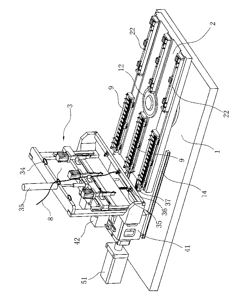
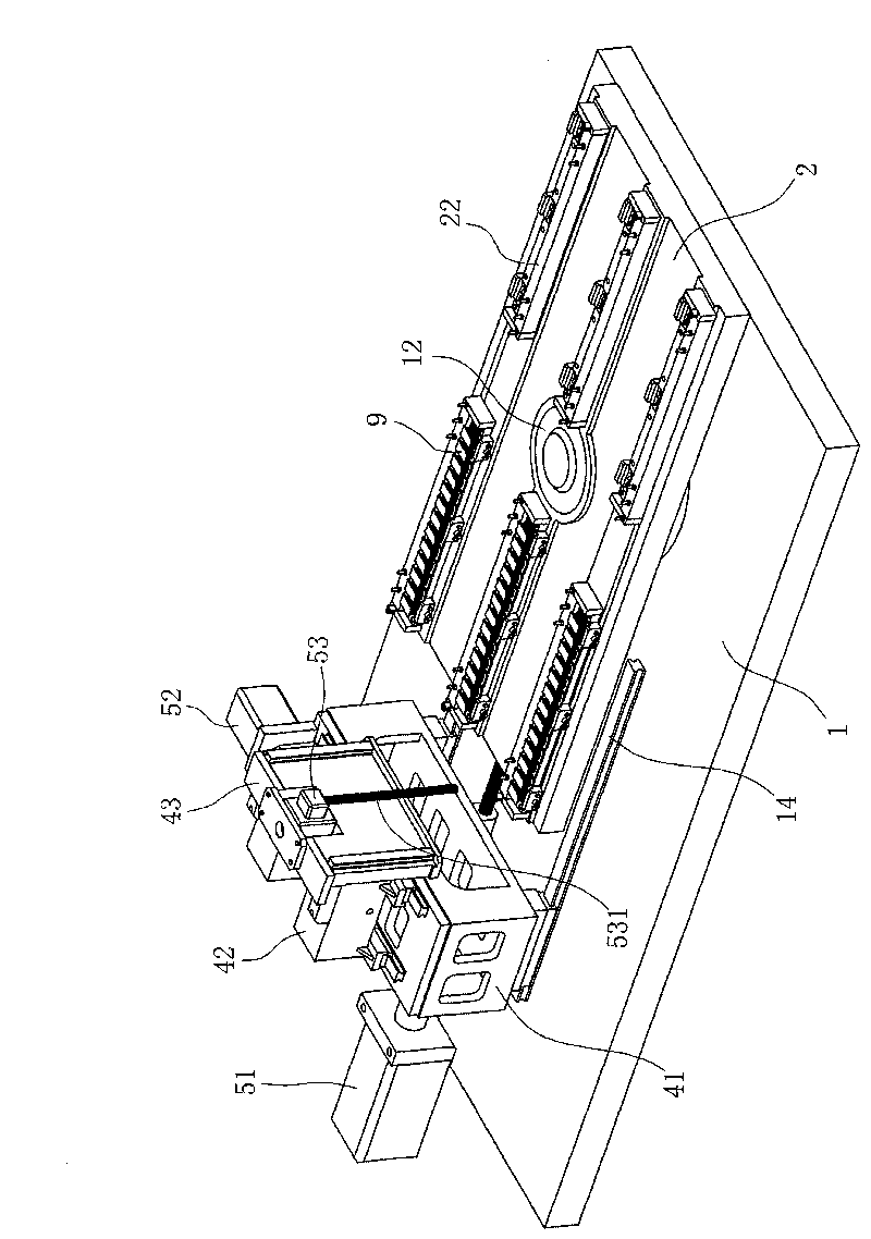
[0035] The winding machine of the present embodiment can realize the automatic winding of the iron core, and the iron core used for winding in the present embodiment can be an in-line or segmented motor core, and the coil of winding adopts enameled wire 8, like Figure 11 As shown, it is a schematic diagram of the structure of the in-line iron core workpiece after the coil winding has been completed. The connected arc-shaped unit tooth blocks 91, two adjacent arc-shaped unit tooth blocks 91 are connected to each other by a connecting part in the direction of the outer edge that can be bent by an external force;

[0036] like Figure 1 to Figure 10 As shown, it is a schematic view of the structure of the winding machine of the embodiment. The winding machine of the present embodiment is arranged in the frame, and the wire wheel for pulling th...


PUM


Abstract

The invention discloses an automatic winding machine of a motor iron core, which comprises a machine frame and a guide roller. The automatic winding machine of the motor iron core is characterized by also comprising a base, a workbench, a winding device and a driving device, wherein the workbench is rotationally connected with the base; a plurality of clamps which are used for clamping in-line or block type iron cores are arranged at the two opposite ends of the workbench; the winding device draws an enameled wire led out by the guide roller and the enameled wire is wound on the in-line or block type iron cores; and the driving device is arranged on the winding device and can perform three-dimensional movement relative to the base so as to control the winding trace of the winding device. Compared with the prior art, the automatic winding machine of the motor iron core adopts the multistage rotary workbench, saves time for mounting workpieces and improves the winding efficiency; and the driving device and the winding device of the automatic winding machine form a three-dimensional movement mechanism to flexibly adjust the coordinates of the thread end of the enameled wire along an X-axis direction, a Y-axis direction and a Z-axis direction, so the winding of coils is easier.

Description

technical field [0001] The invention relates to a winding machine, in particular to an automatic winding machine for a motor iron core. Background technique [0002] The traditional iron core is to make a stamping die according to the shape of the iron core after the design and molding, and then punch and stack the sheets. This method of iron core molding not only has a low material utilization rate, but also has a round shape , The winding space of the inner circular structure groove of the iron core is very small, making the winding more difficult, and the efficiency of the mechanized operation is not high. [0003] The patent number I applied for first is ZL200820082496.1 Chinese utility model patent "A In-line Motor Iron Core" which discloses such an iron core structure. It is characterized in that: the iron core punching sheet is wound by in-line strip-shaped punching sheets, each strip-shaped punching sheet includes several arc-shaped unit tooth blocks connected to ea...

Claims


Application Information

Patent Timeline
IPC IPC(8): H02K15/08
Inventor 晁会岩罗大铖
Owner BOSCH NINGBO E SCOOTER MOTOR
Learn More