Metal wire laying device

A technology of laying device and metal wire, which is applied to electrical components, antennas and other directions, can solve the problems of inability to lay metal wires, low laying efficiency and laying accuracy, and achieves the effect of high laying accuracy and fast speed.

Active Publication Date: 2010-06-23
XIAN AIRCRAFT IND GROUP
View PDF0 Cites 2 Cited by
  • Summary
  • Abstract
  • Description
  • Claims
  • Application Information

AI Technical Summary

Problems solved by technology

[0005] In order to overcome the disadvantages of low laying efficiency and laying accuracy in the prior art, and the inability to lay metal wires on the surface of complex shapes with large curvature, concave and convex, the present invention proposes a metal wire laying device

Method used


Image

  • Metal wire laying device
  • Metal wire laying device
  • Metal wire laying device

Examples


Embodiment Construction

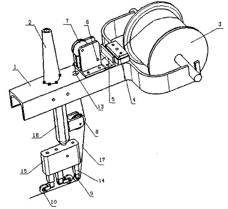
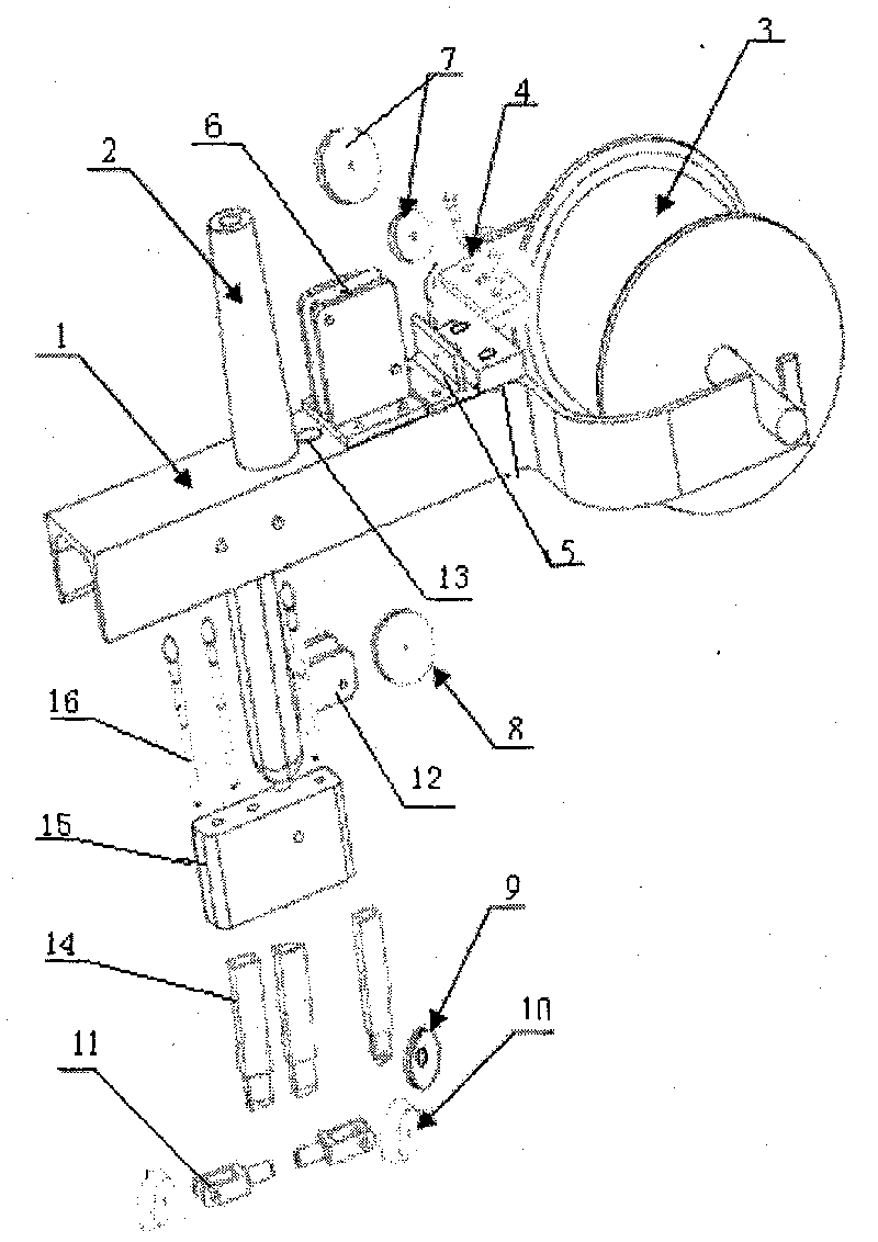
[0020] This embodiment is a wire laying device, which includes a bracket, a wire roller, a tension adjusting plate, a wire mechanism and a wire pay-off mechanism. among them:

[0021] The bracket 1 includes a trough-shaped support rod. At one end of the support rod, a pair of lugs are divided to both sides. The end of the lug has a slot for placing the wire roller 3; the slot is away from the bottom of the lug. The length of is greater than the radius of the wire roller 3, and the width between the two lugs is greater than the axial length of the wire roller 3. The support rod is located at the center of a pair of lugs, and from the position where the support rod and the lugs are adjacent to the end of the support rod, there are tension adjustment plate 4, wire plate 5, double wire wheel group bracket 6, and wire passing Hole 13 and the installation holes of the machine tool connection handle 2, and the positions of the installation holes should be such that the center of the te...


PUM


Abstract

The invention provides a metal wire laying device. A metal wire roller is arranged at one end of a bracket (1); a tension adjusting plate (4), a lead wire plate (5), a dual-lead wire wheel set (7) and a machine tool connecting handle (2) are arranged on the bracket; and a metal wire through hole (13) is arranged between the dual-lead wire wheel set (7) and the machine tool connecting handle (2). A single-lead wire wheel set bracket (12) is arranged at one side of a supporting block connecting rod (18). A wire releasing wheel (9) and a single-lead wire wheel set are arranged on the same vertical plane. A metal wire (17) penetrates the metal wire through hole (13) by the tension adjusting plate, a wire through hole on the lead wire plate and the dual-lead wire wheel set, is laid on the surface of a presoaked cloth on formed tooling equipment through the signal-lead wire wheel set (8) and the wire releasing wheel (9), and is compacted by two wire pressing wheels (10). The metal wire laying device can lay flexible metal wires which are made of different materials and have the diameter of within Phi 0.1mm to Phi 1mm. With high laying precision and speed, the metal wire laying device effectively solves the difficult problem that the metal wire cannot be laid on the surface of a convex-concave complicated body with high curvature.

Description

1. Technical Field [0001] The invention relates to the manufacturing field of non-metallic materials, in particular to a metal wire laying device. 2. Background technology [0002] According to the requirements of the electrical performance of the reflector to intensify the isolation, the copper wires with equal spacing and parallel to each other are laid on the surface of the non-metal composite reflector, and the useful electromagnetic waves are intercepted and reflected according to the different electromagnetic wavelengths. During the laying process, the spacing and parallelism of the metal wires will directly affect the electrical performance of the reflector, that is, the interception and reflection performance of electromagnetic waves. [0003] At present, two methods are usually used to lay metal wires on the surface of the standard parabolic reflector antenna and the surface of the radar antenna. One is the lathe wire method and the other is the manual wire drawing method,...

Claims


Application Information

Patent Timeline
IPC IPC(8): H01Q15/14
Inventor 曹柱子赵建荣田卫袁晓龙
Owner XIAN AIRCRAFT IND GROUP
Why Eureka
Try Eureka