Fatigue test stand of automobile pedals

A technology of fatigue test and automobile pedal, which is applied in vehicle test, impact test, machine/structural component test, etc., to achieve the effect of accurate experimental data, convenient use and simple structure

Inactive Publication Date: 2011-11-02
安徽省华茂汽车附件制造有限公司
View PDF4 Cites 0 Cited by
  • Summary
  • Abstract
  • Description
  • Claims
  • Application Information

AI Technical Summary

Problems solved by technology

[0002]At present, in auto parts manufacturers, there is no special device for the fatigue test of the car pedal, and the existing fatigue test of the car pedal can only use some common shocks The test device is used for testing, and the shortcomings of using a general-purpose impact test device to test the car pedal are: the obtained data is not targeted, the test is more complicated, and the test cost is higher

Method used


Image

  • Fatigue test stand of automobile pedals
  • Fatigue test stand of automobile pedals
  • Fatigue test stand of automobile pedals

Examples


Embodiment Construction

[0012] The present invention is further described below in conjunction with embodiment and accompanying drawing.

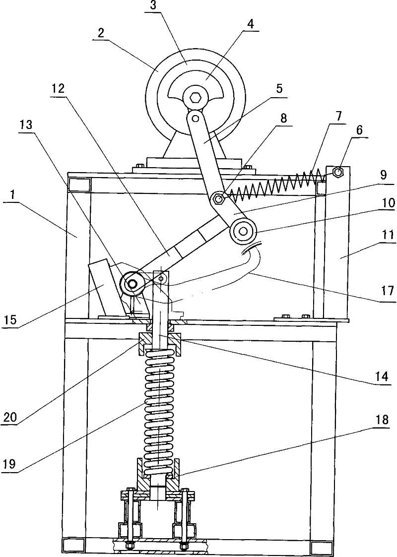
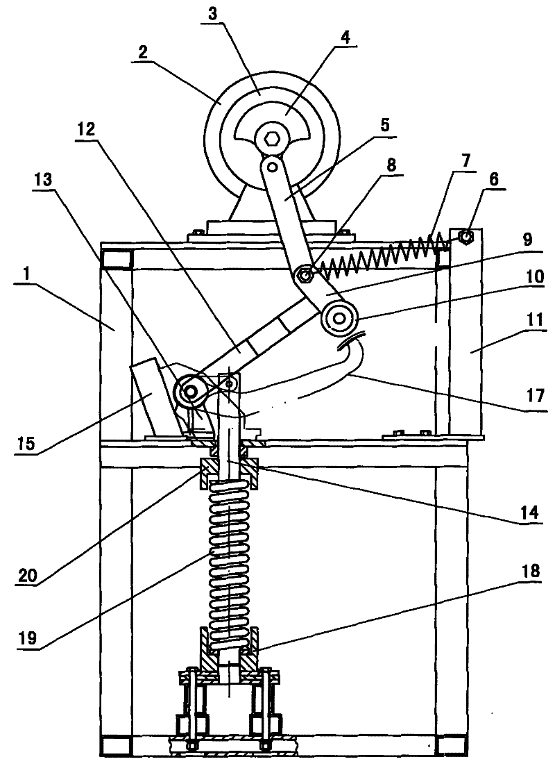
[0013] see figure 1 , figure 2

[0014] The motor 2 provided on the frame 1 of the automobile pedal fatigue test bench is connected with the reducer 3, the output shaft of the reducer 3 is connected with the eccentric wheel 4, the eccentric wheel 4 is hinged with one end of a connecting rod 5, and the working table 16 is located below the speed reducer 3, and a support 13 is fixed on the workbench. One end of a rocker 12 is hinged to the support 13, and the other end of the rocker 12 is connected to a connecting block 9, and the connecting block 9 is connected to the connecting rod. The other end of 5 is hinged, and roller 10 is housed on the connecting block 9 . A pillar 11 is fixed on the workbench 16 , and a spring 7 is connected between the connecting block 9 and the pillar 11 . A pin shaft 14 passes through the workbench 16 . A pair of support frames 1...


PUM


Abstract

A fatigue test stand of automobile pedals is provided with a machine frame and a work stand. A motor arranged on the machine frame is connected with a decelerator. An eccentric wheel is connected to the output shaft of the decelerator, and the eccentric wheel is hinged with one end of a connecting rod. The work stand is arranged below the decelerator, a support is fixed on the work stand, one end of a rocker is hinged with the support, and the other end of the rocker is connected with a connecting block. The connecting block is hinged with the other end of the connecting rod, a roller is arranged on the connecting block, a strut is fixed on the work stand, and the connecting block and the strut are connected by a spring. A hinge pin penetrates through the work stand, a retaining cap is fixed on the upper part of the hinge pin, a spring is sheathed on the hinge pin in a position lower than the retaining cap, and the lower end of the spring is supported by a base fixed on the bottom ofthe machine frame. The present invention has the advantages of simple and reasonable structure, convenient use, accurate and reliable experimental data obtained and low use cost. The present invention provides an ideal fatigue test device for automobile pedals.

Description

technical field [0001] The invention relates to a fatigue test device, in particular to an automobile pedal fatigue test bench. Background technique [0002] At present, in auto parts manufacturing enterprises, there is no special device for the fatigue test of the automobile pedal. The existing fatigue test of the automobile pedal can only be tested by some general impact test devices, and the general impact test device is used to test the automobile pedal. The shortcomings of the test are: the obtained data is not highly targeted, the test is more complicated, and the test cost is higher. Contents of the invention [0003] The object of the present invention is to provide an automobile pedal fatigue test bench, the data obtained by the fatigue test bench testing the automobile pedal is highly pertinent and accurate. [0004] In order to achieve the above object, the present invention adopts the following scheme: automobile pedal fatigue test bench, which has a frame ...

Claims


Application Information

Patent Timeline
Patent Type & Authority Patents(China)
IPC IPC(8): G01M7/08G01M17/007
Inventor 陈义学张付成汤世明
Owner 安徽省华茂汽车附件制造有限公司
Why Eureka
Try Eureka