Heat pump or heat exchange device with periodic positive and reverse pumping

A heat exchange device and pumping technology, applied in the field of heat exchange, can solve problems such as lack of active control, and achieve the effect of reducing the accumulation of impurities or pollutants

Inactive Publication Date: 2014-11-26
杨泰和
View PDF4 Cites 0 Cited by
  • Summary
  • Abstract
  • Description
  • Claims
  • Application Information

AI Technical Summary

Problems solved by technology

[0003] figure 1 It is a schematic block diagram of the main structural principle of a conventional heat pump or heat exchange device with a fixed flow direction; figure 1 As shown in , the primary side fluid (10) is pumped through the primary side fluid pipeline (101) by the one-way fluid pump (120) in a fixed one-way direction, and the primary side fluid (10) passes through the primary side fluid pipeline (101 ) into the pipeline ports on the different temperature side and discharged through the pipeline port on the other side, the secondary side fluid (20) of the secondary side fluid pipeline (102) is also fixed by the one-way fluid pump (120) The flow direction is pumped through the secondary side fluid pipeline (102), and the primary side fluid (10) passing through the primary side fluid pipeline is heated by the solid, liquid or gaseous heat conductor of the heat pump or heat exchange device (100). It can be transmitted, because the flow direction of the primary side fluid (10) passing through the primary side fluid pipeline (101) and the secondary side fluid (20) passing through the secondary side fluid pipeline (102) are fixed, so in the heat pump or In the heat exchange device (100), between the input end and the output end where the primary side fluid pipeline (101) and the secondary side fluid pipeline (102) transfer temperature energy to each other, the relative temperature difference distribution gradient is stable, but No active control function

Method used


Image

  • Heat pump or heat exchange device with periodic positive and reverse pumping
  • Heat pump or heat exchange device with periodic positive and reverse pumping
  • Heat pump or heat exchange device with periodic positive and reverse pumping

Examples


Embodiment Construction

[0211] The method of the present invention will be further described in detail below in conjunction with the drawings and the embodiments of the present invention.

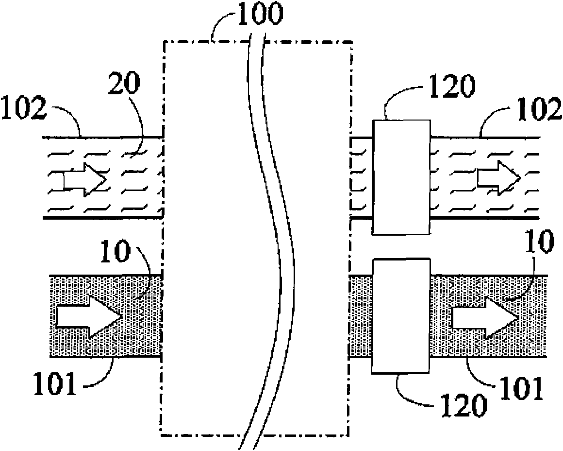
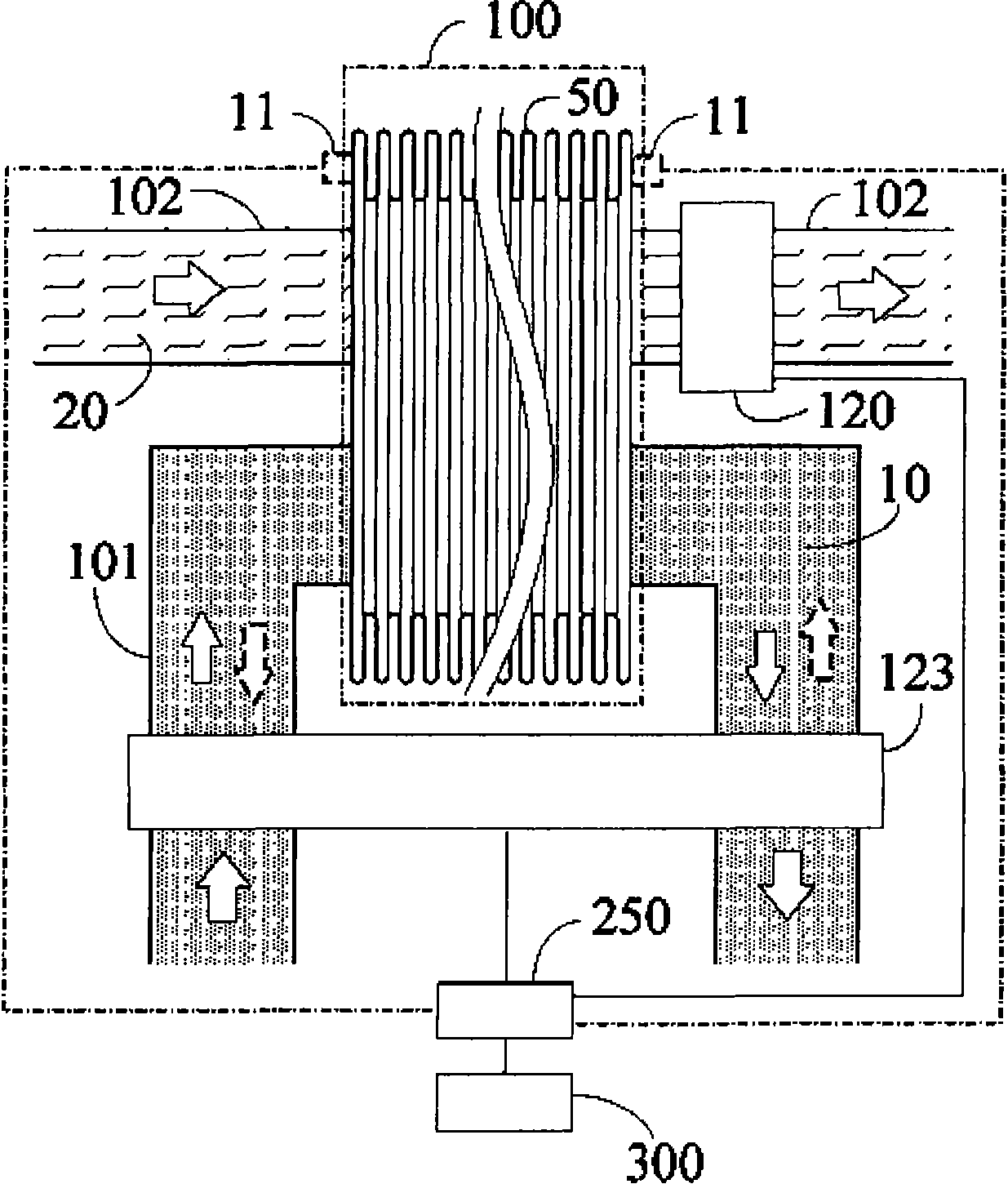
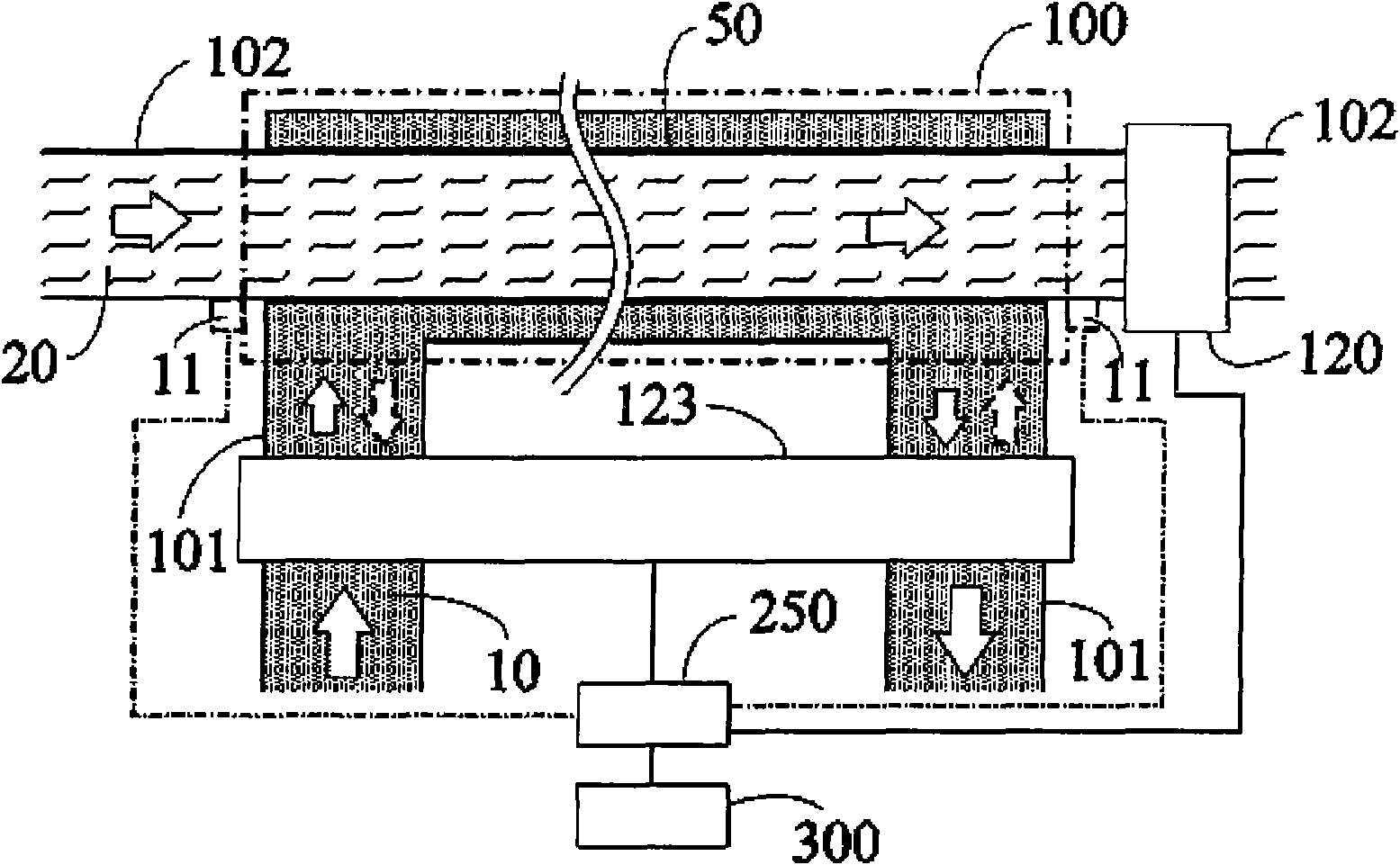
[0212] figure 2 It is a block diagram of the structure principle of the present invention in which the primary-side fluid pipeline and the secondary-side fluid pipeline are jointly arranged on the heat conductor to form a heat pump or heat exchange device function, and are driven by the fluid bidirectional pumping device; figure 2 Shown: This is a heat pump or heat exchange device 100 that pumps in forward and reverse cycles, and is further connected in series to be driven by a power source 300 and controlled by a fluid cycle reversing control device 250 to pump fluid in cycles forward and reverse. The moving device 123 is used to make the pumped flow through the primary fluid pipeline 101, and the primary fluid 10 through the heat pump or the heat exchange device 100 changes its flow direction periodically; wherein:...


PUM


Abstract

The present invention discloses that the conventional applications for heat pump or heat exchange devices are further made to be the functional structure having periodic positive and reverse directional pumping, wherein either one of the pumping flow directions of the primary side fluid piping for passing by primary side fluid or secondary side fluid piping for passing by secondary side fluid are driven by the periodic positive and reverse flow directional pump to timely improve the temperature distribution status between the primary side fluid and secondary side fluid as well as reduce the defects of impurity accumulations in fixed flow directions.

Description

Technical field [0001] The present invention relates to the field of heat exchange technology, and in particular to a heat pump or heat exchange device pumped in forward and reverse cycles. Background technique [0002] A traditional heat pump or heat exchange device, which is only used for the primary side pipeline through the primary side fluid, or the secondary side pipeline through the secondary side fluid, is used to pump the fluid in the fluid pipeline by using a pumping device The pump works in a fixed direction, so that the fluid takes away heat for heat exchange, and changes the temperature distribution state of the fluid pipeline. [0003] figure 1 It is a block diagram of the main structure principle of a traditional heat pump or heat exchange device with a fixed flow direction; figure 1 As shown in the figure, the primary fluid (10) is pumped through the primary fluid line (101) by a one-way fluid pump (120) in a fixed single flow direction, and the primary fluid (10) p...

Claims


Application Information

Patent Timeline
Patent Type & Authority Patents(China)
IPC IPC(8): F28F27/00
CPCF25B30/00F04F1/00F04F5/50F28F19/00F25B41/00
Inventor 杨泰和
Owner 杨泰和
Why Eureka
Try Eureka