Deep well drilling waterpower deslagging device of floor anchor rod hole of tunnel

A deep hole drilling and bolt hole technology, which is applied in the installation of bolts, shaft equipment, earth-moving drilling, etc., can solve the problems of restricting the increase of the drilling speed of bolt holes and poor slag discharge effect.

Inactive Publication Date: 2010-06-23
HENAN POLYTECHNIC UNIV
View PDF0 Cites 9 Cited by
  • Summary
  • Abstract
  • Description
  • Claims
  • Application Information

AI Technical Summary

Problems solved by technology

[0003] In view of the above situation, in order to overcome the defects of the prior art, the object of the present invention is to provide a hydraulic slag discharge device for deep hole drilling of rock bolt holes in the roadway floor, which can effectively solve the problem of slag discharge during the drilling process of the rock bolt hole drilling equipment in the floor. The effect is poor, which restricts the problem of increasing the drilling speed of the bolt hole. The technical solution is that there is a drill pipe with both ends protruding from the sleeve inside the sleeve, the upper end of the drill pipe is connected with the upper interface connector, and the lower end of the drill pipe is connected with the The lower interface connecting piece is connected, and the upper and lower ends of the drill pipe are fixed together with the sleeve through the sealed bearing and the bearing sleeve connecting piece, forming a slag discharge structure with drainage and slag discharge channels. Surrounding ring ribs, there is a water inlet channel in the drill pipe, and the slag discharge structure is connected to each other through the sleeve connecting pipe

Method used


Image

  • Deep well drilling waterpower deslagging device of floor anchor rod hole of tunnel
  • Deep well drilling waterpower deslagging device of floor anchor rod hole of tunnel
  • Deep well drilling waterpower deslagging device of floor anchor rod hole of tunnel

Examples


Embodiment Construction

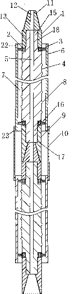
[0010] The specific implementation manners of the present invention will be described in detail below in conjunction with the accompanying drawings.

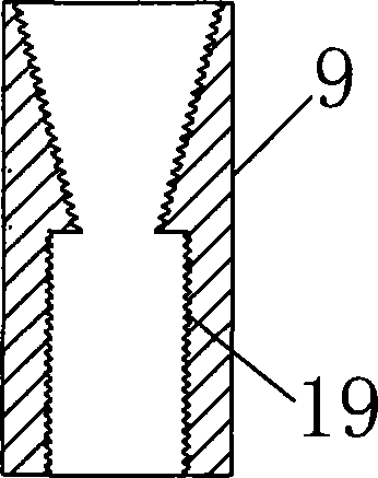
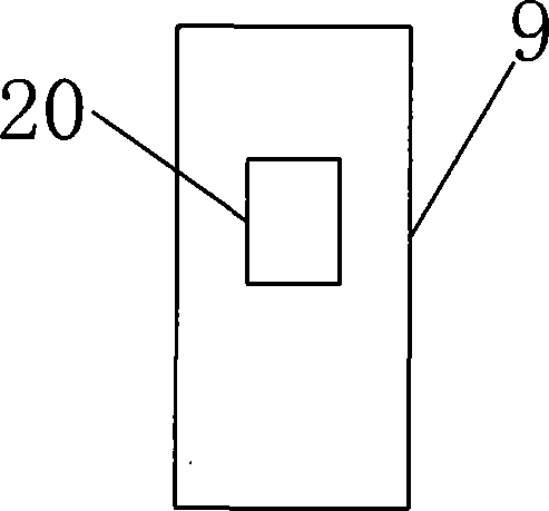
[0011] Depend on Figure 1-Figure 6 Given, the structure of the present invention is that there is a drill rod 4 with two ends extending out of the sleeve in the sleeve 6, the upper end of the drill rod 4 is connected with the upper interface connector 1, the lower end of the drill rod is connected with the lower interface connector 9, and the drill rod 4 is connected with the upper interface connector 1. The upper and lower ends of the rod 4 are fixed together with the sleeve 6 through the sealed bearing 2 and the bearing sleeve connector 3 to form a slag discharge structure with a drainage and slag discharge channel 7. There is a spiral surrounding the drill pipe 4 The ring rib 8 and the drill pipe 4 have a water inlet channel 5, and the slag discharge structure is connected to each other through the sleeve connecting pipe 10....


PUM


Abstract

The invention relates to a deep well drilling waterpower deslagging device of a floor anchor rod hole of a tunnel, which effectively solves the difficulties that the deslagging effect in the drilling process of a floor anchor rod hole drilling device and the increase of the drilling rate of the anchor rod hole is restricted. The invention has the technical scheme that a drill pipe both ends of which extend out of a sleeve is arranged in the sleeve, the upper end of the drill pipe is connected with an upper connector connecting piece, the lower end of the drill pipe is connected with a lower connector connecting piece, the upper end and the lower end of the drill pipe and the sleeve are fixed together via a closed-type bearing and a bearing sleeve connecting piece to form a deslagging structure with a dewatering and deslagging channel, the periphery wall of the drill pipe is provided with a spirally wound annular rib, a water inlet channel is arranged in the drill pipe, and the deslagging structures are connected with each other via a sleeve connecting pipe. The invention has the advantages of simple structure, convenient operation and good deslagging effect, greatly increases the drill rate and hole forming depth of the floor anchor rod, and is innovative on a deslagging device.

Description

1. Technical field [0001] The invention relates to a slag discharge device, in particular to a hydraulic slag discharge device for deep hole drilling of anchor rod holes on the roadway bottom plate. 2. Background technology [0002] At present, the bottleneck of the deep hole drilling method for the roadway floor bolt hole in coal mines is the difficulty of rapid slag removal. There are three main methods for slag discharge in the floor bolt hole drilling method: ①Drilling with a roof bolt rig, through Slagging is carried out by means of high-pressure air blowing; ②Drilling is carried out by using a coal electric drill and its matching twist drill pipe, and the slag is discharged by the rotation of the twist drill pipe; ③Drilling is carried out by using a full hydraulic tunnel drilling rig with high propulsion. However, the common disadvantage of the first and second methods is that the slag cannot be completely discharged, resulting in slow drilling speed and shallow drilli...

Claims


Application Information

Patent Timeline
Patent Type & Authority Applications(China)
IPC IPC(8): E21D20/00E21D7/00
Inventor 刘少伟张辉许莉莉李小军郑新旺董士举张伟光
Owner HENAN POLYTECHNIC UNIV
Why Eureka
Try Eureka