
Connecting rod automation electro-brush plating machine tool

A technology of brush plating and connecting rod, which is applied in the field of brush plating, can solve the problems of inability to guarantee qualified products, difficulty in cleaning, and low efficiency of brush plating, so as to improve the work efficiency of brush plating, improve the quality of coating, and the efficiency of brush plating Improved effect

Inactive Publication Date: 2011-03-16
ACADEMY OF ARMORED FORCES ENG PLA
View PDF1 Cites 5 Cited by
  • Summary
  • Abstract
  • Description
  • Claims
  • Application Information

AI Technical Summary

Problems solved by technology

[0006] One is the low efficiency of brush plating
Manual brush plating can only brush one plating pen at a time, and it cannot be brushed and plated in batches, which cannot meet the requirements of the workpiece repair industry
[0007] Second, brush plating standards are not uniform
Since brush plating is a manual operation with strong randomness and high technical requirements for workers, the qualification rate of brush plating workpieces will also be affected
[0008] Third, the waste of plating solution is serious
With the prolongation of the brush plating time, the concentration of metal ions in the plating solution decreases, but when the concentration of metal ions drops to about 40% of the original concentration, it is impossible to continue to obtain a qualified coating. In this case, the plating solution has to be scrapped. And at this moment, also have about 40% metal (generally nickel) in the plating bath to be unused, cause very big waste
[0009] Fourth, the plating pen needs to be replaced many times
The brush plating process includes multi-step processes such as electric cleaning, strong activation, weak activation, bottom layer and plating working layer. Since the plating solutions cannot be confused with each other, and the residual liquid in the coating material of the plating pen is difficult to clean, so In the brush plating process, the plating pen needs to be replaced in each step, which is extremely inconvenient to realize automatic brush plating
[0010] Fifth, the precision of parts clamping is high
[0011] Sixth, brush plating temperature is too high
At the same time, due to the small amount of plating solution contained in the parts during brush plating, the circulation of the plating solution is not smooth, so the heat generated by brush plating cannot be released and cooled in time, causing the temperature to rise rapidly and burn the coating
[0012] Seven is the higher cost
[0014] However, after long-term research, the inventor found that there are still many problems in the above-mentioned device, such as the combination of the rotation of the plating pen and the reciprocating motion of the base is not good, which makes the effect of brush plating not good.
In addition, the brush plating process requires multiple liquid changes and rinses. Due to the movement of the base, these procedures must be implemented in a static environment, and the efficiency is further limited.
The movement of the base is also likely to cause splashing of the plating solution, and problems such as poor sealing and loosening of the connecting rod connection
[0015] To sum up, the traditional method can no longer meet the requirements of automatic brush plating of inner holes, and even cannot guarantee qualified products, so it needs to be improved and enhanced.

Method used


Image

  • Connecting rod automation electro-brush plating machine tool
  • Connecting rod automation electro-brush plating machine tool
  • Connecting rod automation electro-brush plating machine tool

Examples


Embodiment 1

[0044] Embodiment 1 machine tool structure of the present invention

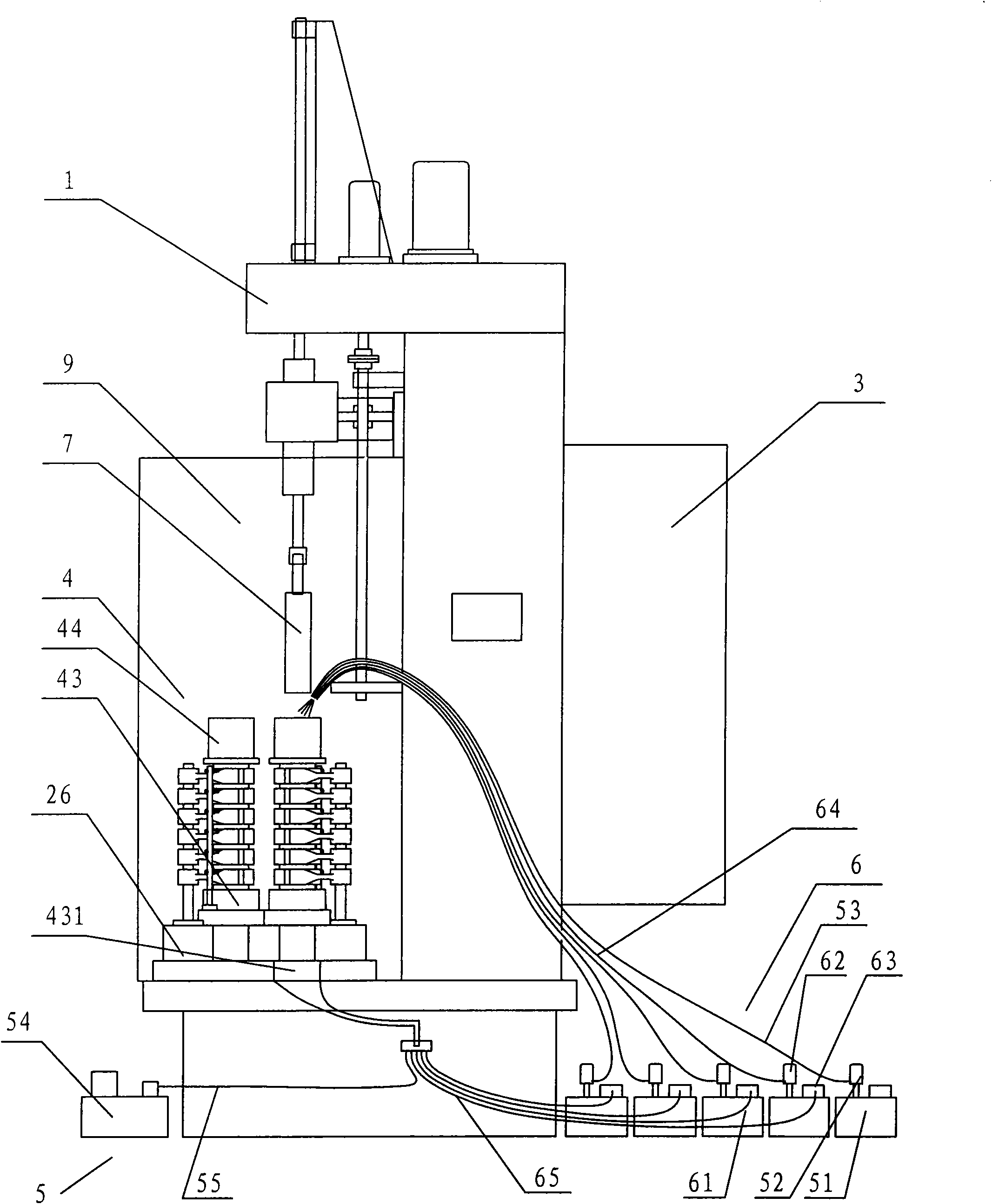
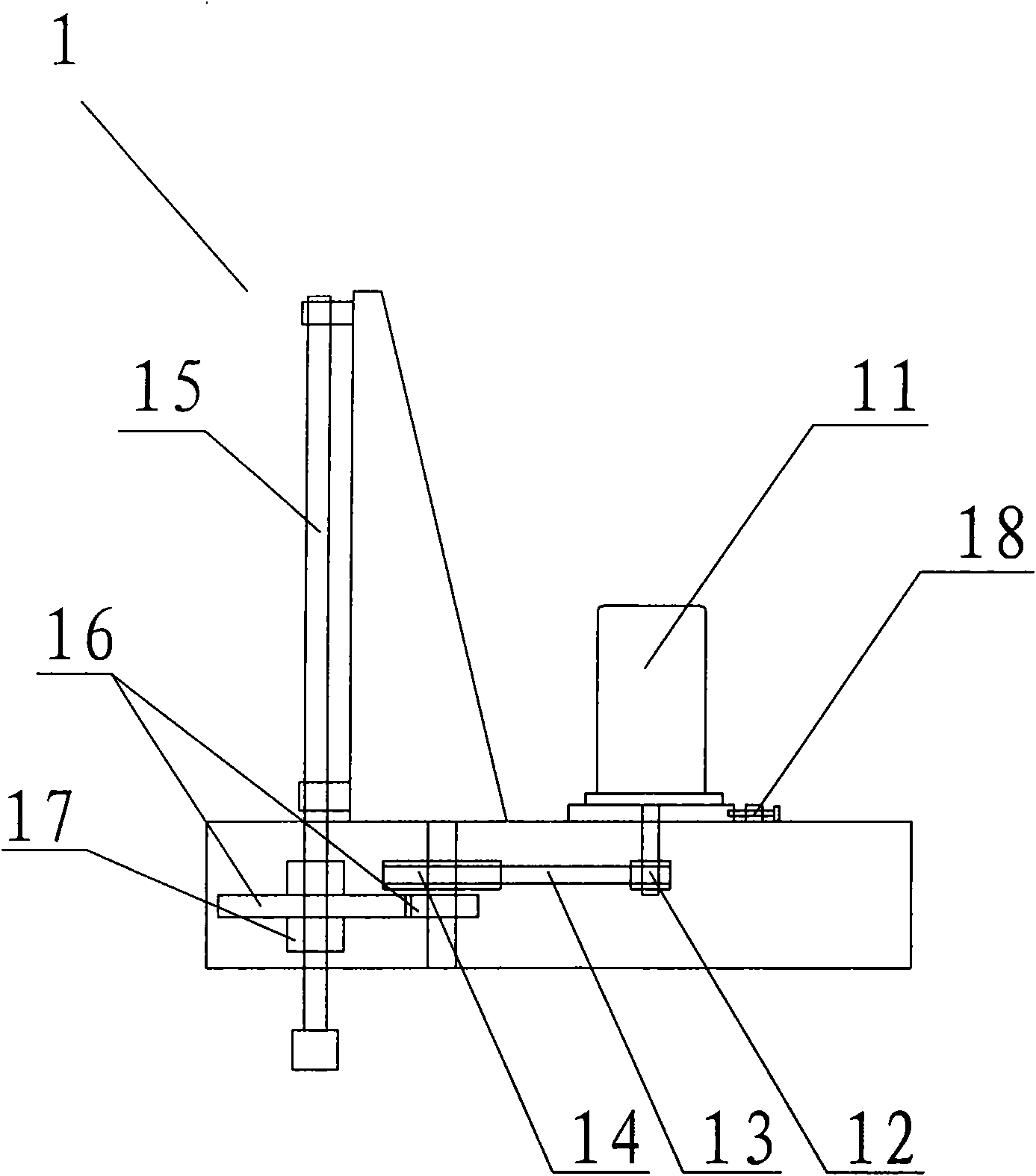
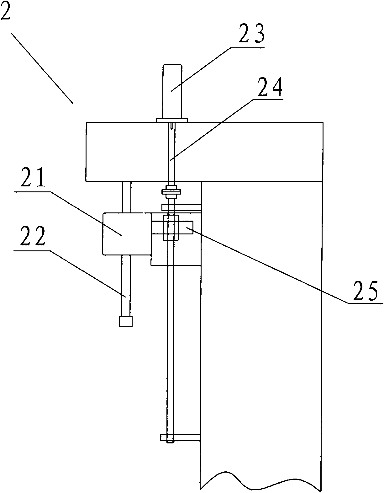
[0045] Such as Figure 1 to Figure 5 As shown, a connecting rod automatic brush plating machine tool includes a main rotation transmission device 1, a plating pen advance and retreat device 2, an electric control device 3, two sets of clamp devices 4, a flushing system 5 and a liquid supply recovery system 6;

[0046] The main rotation transmission device 1 is provided with a main rotation motor 11 on a motor base, the main rotation motor 11 is connected with the driving pulley 12, and the driving pulley 12 is connected with the driven pulley 14 through the timing belt 13; a rolling spline pair 15 is connected to the driven pulley 14 through the gear 16; the outer sleeve of the rolling spline pair 15 is provided with a shaft sleeve 17;

[0047] The spindle box 21 of the plating pen advance and retreat device 2 is connected with the rolling spline pair 15 on the main rotation transmission device 1 through th...

Embodiment 2

[0057] Embodiment 2 The specific brush plating method of the machine tool of the present invention

[0058] a. Parts installation: the fixture device is set on the base, which is an insulating board. The fixture device is equipped with a small connecting rod hole fixed mandrel, a connecting rod large hole rough positioning device and a support seat; when clamping, the small holes of the six connecting rods are placed on the connecting rod small hole fixed mandrel in turn, and the connecting rod The end of the large hole leans against the rough positioning device for the large hole of the connecting rod.

[0059] b. Alignment of parts: make a mandrel for the large hole of the connecting rod, whether the mandrel matches the shape and size of the connecting rod, and the upper end of the mandrel is connected to the main shaft. After the connecting rod is roughly positioned, start the machine tool, and first return the machine tool to zero (returning to zero means that the spindle...


PUM


Abstract

The invention relates to an inner bore part, in particular to a connecting rod automation electro-brush plating machine tool; the machine tool is mainly used for the inner bore parts and is suitable for strengthening of new products and is used for repairing and remanufacturing wear-out parts; the invention discloses a connecting rod automation electro-brush plating machine tool, comprising a main spinning transmission device, a plating pen driving and reversing device, an electric control device, a flushing system and at least one feed liquid recovery system; the machine tool can realize automatic brush-plating process and rapidly brush-plating the connecting rod on a large scale, while the working efficiency is improved, the using amount of plating liquid can be saved, the using mount of the plating pen is reduced and the brush-plating cost is reduced.

Description

technical field [0001] The invention relates to an electric brush plating technology, in particular to a machine tool for electric brush plating of inner hole parts, especially connecting rods. The machine tool is aimed at parts with inner holes, and it is not only suitable for strengthening new parts, but also for repairing and remanufacturing of worn parts. Background technique [0002] Brush plating is a surface processing technology that uses electrochemical methods to reduce metal ions to metal and deposit them on the surface of metal or non-metal products to form a smooth and dense metal coating that meets the requirements. With the development of science and technology and production, brush plating technology involves more and more fields, and people's requirements for coating are getting higher and higher. At present, the application of metal coating has spread all over the various production and research departments of economic activities, and has great significanc...

Claims


Application Information

Patent Timeline
Patent Type & Authority Patents(China)
IPC IPC(8): C25D5/06
Inventor 徐滨士胡振峰董世运吴斌杨华汪笑鹤
Owner ACADEMY OF ARMORED FORCES ENG PLA
Learn More