
Low voltage differential signal driver adaptive to various IO power supplies

A low-voltage differential, signal driver technology, applied in the direction of logic circuit coupling/interface, logic circuit connection/interface layout using field effect transistors, etc. Problems such as insufficient description

Active Publication Date: 2010-06-16
SANECHIPS TECH CO LTD
View PDF0 Cites 16 Cited by
  • Summary
  • Abstract
  • Description
  • Claims
  • Application Information

AI Technical Summary

Problems solved by technology

For example, there is a technology using a low-voltage LVDS driver in the prior art, which uses a switchable current source to control the LVDS switch tube. Although it can be used in low-voltage applications, the common-mode voltage output by an LVDS driver It is easy to be unstable. If a common-mode feedback circuit is used, the requirements for the common-mode feedback circuit are higher; second, the description of the bias is not enough, resulting in high-voltage and low-voltage may not be used at the same time

Method used


Image

  • Low voltage differential signal driver adaptive to various IO power supplies
  • Low voltage differential signal driver adaptive to various IO power supplies
  • Low voltage differential signal driver adaptive to various IO power supplies

Examples


Embodiment Construction

[0019] Below in conjunction with accompanying drawing, the present invention will be described in further detail.

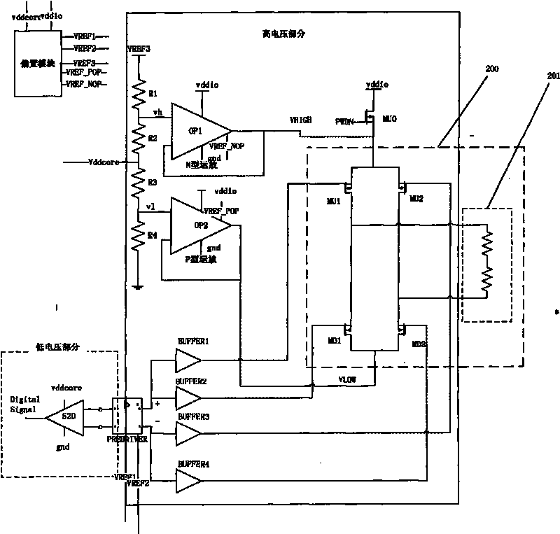
[0020] Such as figure 1 On the whole, the LVDS driver of the present invention includes: a differential conversion module S2D connected to digital signals, a pre-amplifier PREDRIVER following S2D, and a driving amplifier circuit 200 . The differential conversion module is used to convert the low-voltage digital signal of the core into a differential voltage signal; the pre-amplifier is used to amplify the differential voltage signal and output positive and negative voltage signals; the drive amplifier circuit is used to amplify the pre-amplifier The positive and negative output signals of the two channels are amplified to obtain the output of the driver.

[0021] Such as figure 1 The buffers BUFFER1, BUFFER2, BUFFER3 and BUFFER4 constitute a buffer unit connected in series between the output terminal of the pre-amplifier and the input terminal of the driving am...


PUM


Abstract

The invention discloses a low voltage differential signal driver adaptive to various IO power supplies. The low voltage differential signal driver comprises a differential conversion module, a pre-amplifier and a driving amplification circuit, wherein the differential conversion module is used for converting a low-voltage digital signal of a core into a differential voltage signal; the pre-amplifier is used for amplifying the differential voltage signal and outputting a positive path of voltage signals and a negative path of voltage signals; and the driving amplification circuit is used for amplifying the positive and negative paths of output signals of the pre-amplifier to obtain the output of the driver. The low-voltage differential signal driver automatically changes through bias along with the power supply and changes the control range of operational amplification to form a new circuit device. The low voltage differential signal driver is adapted to a microelectronic circuit of which core voltage is changed from low voltage 0.9 V to 1.5 V and IO voltage is changed from 1.8 V to high voltage 5 V through a topological structure where a low voltage core circuit and a high voltage IO circuit are separated and the bias which comes from the low voltage of the core and is flexibly adapted to the high voltage of the IO power supply, can be used for a multi-path LVDS driver and can transmit data at a rate of 1 G bit per second (bps).

Description

technical field [0001] The invention relates to a circuit of a deep submicron LVDS (Low Voltage Differential Signal, low voltage differential signal) driver, in particular to a microelectronic circuit of an LVDS driver adaptable to various IO power sources. Background technique [0002] In the design of modern electronic circuits, a large number of differential lines are used to carry long-distance high-speed signals within the board or between boards, and the LVDS differential line is the most used. However, as the power supply voltage of the integrated circuit decreases, the core (core) voltage of the integrated circuit can drop very quickly and become very small, but the IO voltage drops more slowly than the core voltage, and the drop rate of the two is not proportional. [0003] Therefore, in order to adapt to the gap between the core voltage and the IO voltage, people can only constantly modify the circuit of the LVDS driver, such as the redesign of the bias, which brin...

Claims


Application Information

Patent Timeline
Patent Type & Authority Applications(China)
IPC IPC(8): H03K19/0175H03K19/0185
Inventor 易律凡
Owner SANECHIPS TECH CO LTD
Learn More