Motor shaft replacing tool and shaft replacing method thereof

A technology for motor shafts and tools, which is applied in the manufacture of motor generators, electrical components, electromechanical devices, etc. It can solve the problems of winding insulation damage, safety and reliability cannot be guaranteed, clamping, hoisting, turning over and other problems, and achieves a simple structure , The effect of clamping the rotor iron core is stable and safe, and the method of shaft replacement is convenient

Active Publication Date: 2010-06-16
昆明电机厂有限责任公司
View PDF0 Cites 5 Cited by
  • Summary
  • Abstract
  • Description
  • Claims
  • Application Information

AI Technical Summary

Problems solved by technology

In the prior art, the shaft replacement of the rotor of the wound rotor motor is based on the structure of the rotor, and the rotor is pressed from the ventilation hole with bolts, or the rotor is clamped from the inner circle with a clip, which is inconvenient for clamping, hoisting and turning over. Moreover, the safety and reliability cannot be guaranteed, and it is very easy to cause damage to the winding insulation and fall short.
In order to ensure the recovery of the function of the motor after the repair, during the shaft replacement process, the original winding insulation must be protected from damage, the lamination coefficient of the iron core will basically remain unchanged, and it is also convenient for clamping, hoisting and turning over. Technology is more difficult to meet these requirements

Method used


Image

  • Motor shaft replacing tool and shaft replacing method thereof
  • Motor shaft replacing tool and shaft replacing method thereof
  • Motor shaft replacing tool and shaft replacing method thereof

Examples


Embodiment Construction

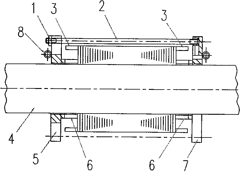
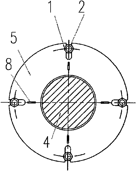
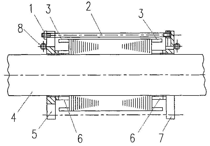
[0018] As shown in the figure, the shaft changing tool of the present invention includes a symmetrical upper pressing plate 5 and a lower pressing plate 7 with a central hole, a symmetrical adjustable pull rod 2, and the upper pressing plate 5, the lower pressing plate 7, and the pulling rod 2 are connected to form a fixed frame structure. The distance between the upper pressing plate and the lower pressing plate can be adjusted by adjusting the pull rod 2 . The two ends of the pull rod 2 in this embodiment are screw rods, one end of which is fitted and connected with the screw hole on the upper platen or the lower platen, and the other end passes through the connecting hole on the lower platen or the upper platen and is connected by the nut 1. The distance between the upper pressing plate and the lower pressing plate can be adjusted. The diameter of the central hole of the upper pressing plate and the lower pressing plate cannot be smaller than the diameter of the rotating sh...


PUM


Abstract

The invention relates to a motor shaft replacing tool and a shaft replacing method thereof. A fixing framework of the shaft replacing tool consists of an upper press plate (5), a lower press plate (7) and a pull rod (2), wherein the upper press plate (5) and the lower press plate (7) are symmetrical and are provided with center holes. The diameter of the center holes of the upper press plate and the lower press plate is not smaller than the diameter of a motor rotary shaft. The insides of the upper press plate and the lower press plate are symmetrically provided with clamping pieces (6) which are arranged besides the center holes, and the height of the clamping pieces is higher than a winding end (3) of a motor rotor. The shaft replacing method has the following steps of: sheathing the upper press plate and the lower press plate on the motor rotary shaft from both ends of the rotor through the center holes; clamping a rotor core by the clamping pieces; disassembling an axial positioning circular key from the motor rotary shaft; pressing the motor rotary shaft out; pressing the new motor rotary shaft into the center holes of the lower press plate, the rotor core and the upper press plate; installing the axial positioning circular key; and disassembling the shaft replacing tool. The invention is convenient to replace the rotary shaft of the motor rotor, is difficult to damage the winding insulation of the motor rotor, and is safe and reliable.

Description

technical field [0001] The invention belongs to the technical field of motor shaft exchange. Background technique [0002] High voltage wound rotor motors are widely used in actual production because of their excellent starting performance. Due to the long-term alternating heavy load operation of this type of motor, the bearings and rotating shafts of the shaft system are more prone to failure. If the bearing fails, it is easier to replace it. The rotating shaft is prone to bending deformation, crack deformation and even breakage. If these failures occur, the rotating shaft can only be replaced. [0003] The rotor structure of the high-voltage wound rotor motor is special. The manufacturing process is to first laminate the stamping sheet on the shaft, and then carry out the embedding, insulation and dynamic balancing treatment. In the prior art, the shaft replacement of the rotor of the wound rotor motor is based on the structure of the rotor, and the rotor is pressed fro...

Claims


Application Information

Patent Timeline
Patent Type & Authority Applications(China)
IPC IPC(8): H02K15/00
Inventor 胡东声刘金华
Owner 昆明电机厂有限责任公司
Why Eureka
Try Eureka