
Method for charging storage battery by using solar energy and charging mains supply by using pulse current

A technology for solar panels and batteries, applied in battery circuit devices, current collectors, electric vehicles, etc., to achieve excellent functions, low manufacturing costs, and significant economic and social effects.

Inactive Publication Date: 2012-06-27
SUZHOU MEIYANG NEW ENERGY TECH
View PDF0 Cites 0 Cited by
  • Summary
  • Abstract
  • Description
  • Claims
  • Application Information

AI Technical Summary

Problems solved by technology

It can be seen that the design structure must fully solve the heat dissipation problem of D1

Method used


Image

  • Method for charging storage battery by using solar energy and charging mains supply by using pulse current
  • Method for charging storage battery by using solar energy and charging mains supply by using pulse current
  • Method for charging storage battery by using solar energy and charging mains supply by using pulse current

Examples


Embodiment Construction

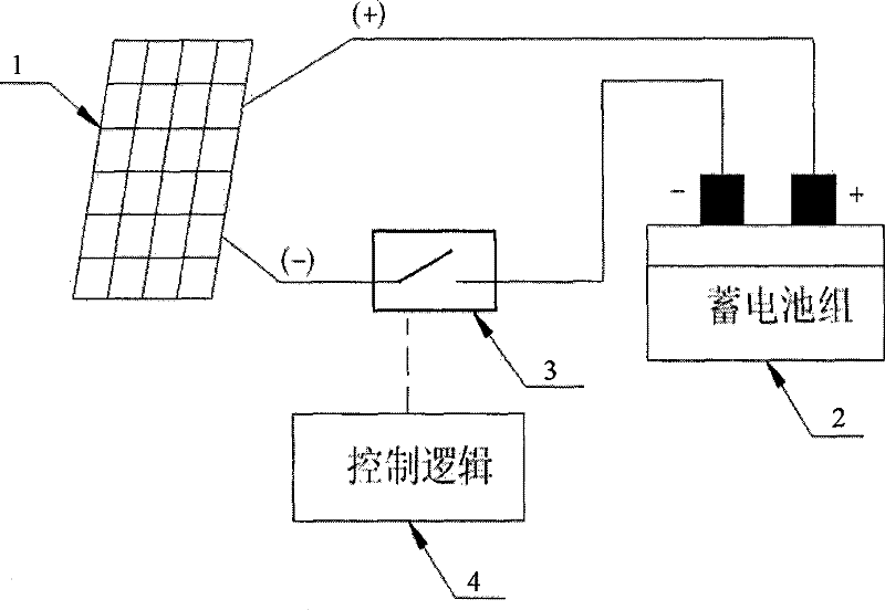
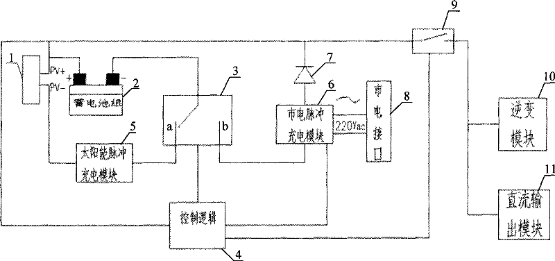
[0017] Such as figure 2 , image 3 As shown, the solar charging system of the storage battery and the mains pulse charging system, the solar panel 1 converts light energy into electrical energy, and the storage battery 2 is used to store electrical energy and supply energy to the load at the same time, including the solar charging circuit and the mains charging circuit, solar charging The circuit is composed of solar panel 1, bidirectional switch 3, solar pulse charging module 5, and control logic 4. The mains charging circuit is composed of mains interface 8, mains pulse charging module 6, anti-reverse charging diode 7, bidirectional switch 3, control Logic 4 constitutes. The positive pole of the solar battery panel 1 is directly connected to the positive pole of the battery 2 , and the negative pole of the solar battery panel 1 is connected to the negative pole of the battery 2 through the solar pulse charging module 5 and the bidirectional switch 3 . The mains interface ...


PUM


Abstract

The invention relates to a method for charging a storage battery by using solar energy and charging a mains supply by using pulse current. The anode of a solar battery panel is directly connected with the anode of the storage battery, and the cathode of the solar battery panel is connected with the cathode of the storage battery through a solar and pulse charging module and a two-way switch; a mains supply interface is connected with the pulse charging module of the main supply, the anode of the pulse charging module of the main supply is connected with the anode of the storage battery through a reverse charging-preventing diode, and the cathode of the pulse charging module of the main supply is connected with the cathode of the storage battery through the two-way battery; and control logic is respectively connected with the anode of the storage battery, the two-way switch, the pulse charging module of the mains supply and an output switch circuit. Under the condition of having no themains supply, the two-way switch is pushed to the 'a' state, a solar charging loop is formed, and then the solar and pulse charging mode is formed; after the mains supply is switched on, the two-way switch is switched to the 'b' state, and then a mains supply charging loop is formed. By adopting a co-anode solar charging structure, the method greatly enhances charging efficiency, reduces the requirement of heat dissipation and is very practical.

Description

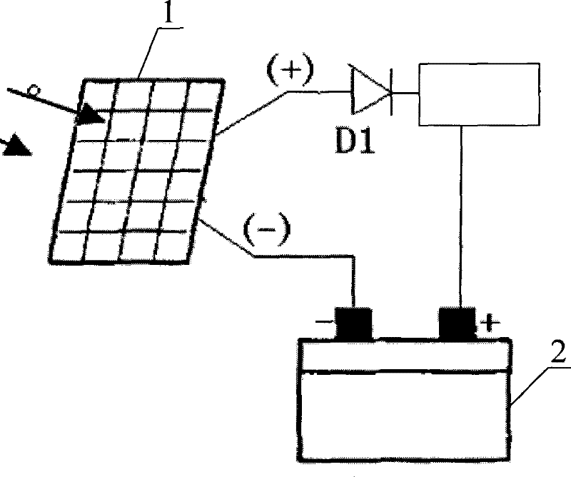
technical field [0001] The invention relates to a charging method, in particular to a storage battery charging method with solar charging and commercial power pulse charging. Background technique [0002] At present, the solar photovoltaic power supply solar silicon panel charges the battery charging circuit, usually as figure 1 As shown, the negative pole of the solar cell panel (1) is short-circuited with the negative pole of the storage battery (2), and the positive pole (PV+) of the solar cell panel (1) is connected to the positive pole of the storage battery (2) through an anti-reverse charging diode and other related circuits. This structure is relatively easy to realize anti-reverse charging through the diode D1, and the voltage of the solar cell can drop below the voltage of the storage battery without being affected by the voltage of the storage battery, and it is easy to realize light control. [0003] However, when this structure is charging, there is always a vo...

Claims


Application Information

Patent Timeline
Patent Type & Authority Patents(China)
IPC IPC(8): H02J7/00H02J7/02H02J7/35
Inventor 谭一云赵喜燕
Owner SUZHOU MEIYANG NEW ENERGY TECH
Learn More