
Permanent magnet energy-saving contactor

A technology of contactors and permanent magnets, applied in the direction of electromagnetic relays, electromagnetic relay details, relays, etc.

Active Publication Date: 2020-05-01
浙江亚泰电力科技有限公司
View PDF3 Cites 0 Cited by
  • Summary
  • Abstract
  • Description
  • Claims
  • Application Information

AI Technical Summary

Problems solved by technology

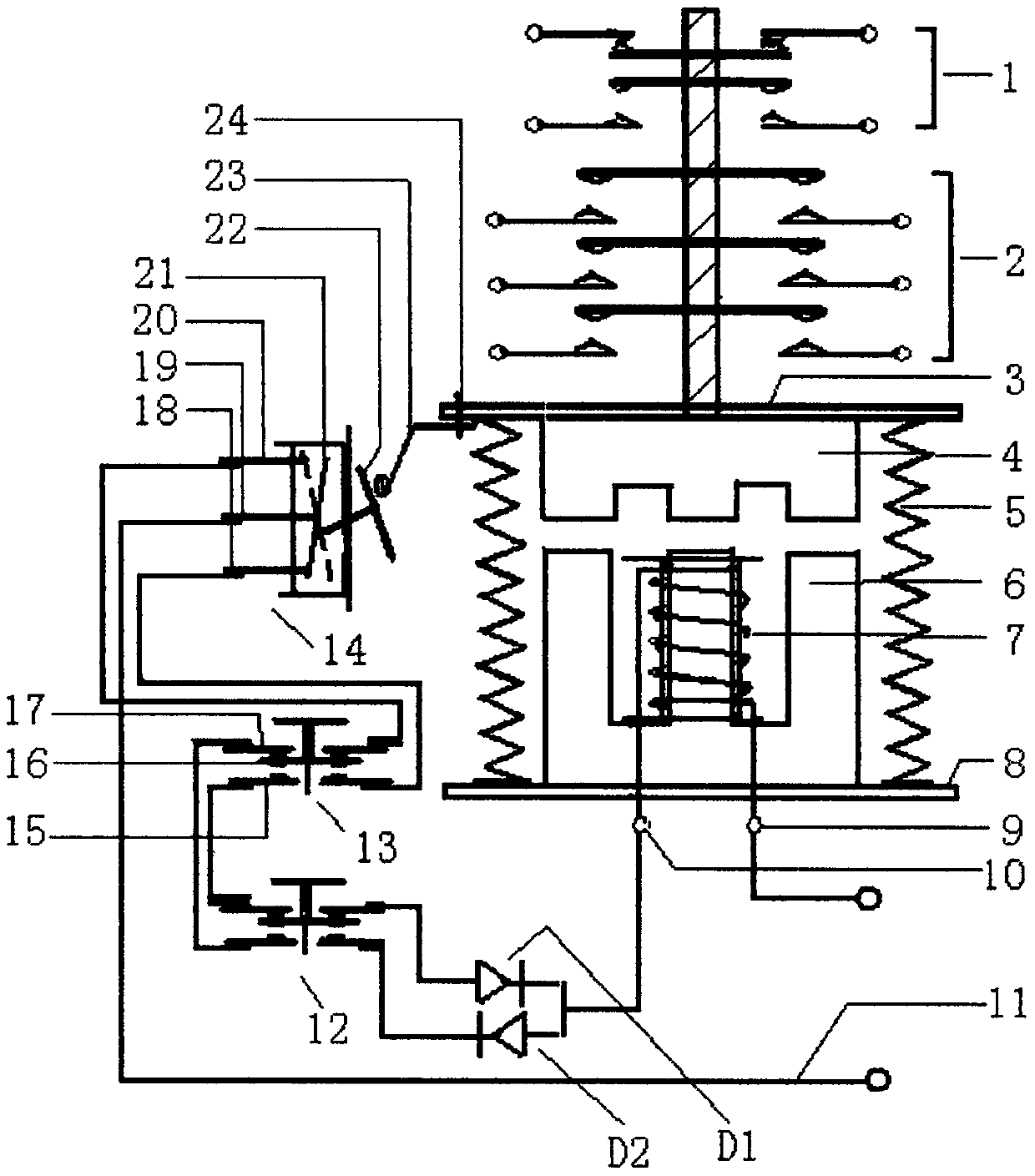
[0003] In order to overcome the defects of electric energy consumption and electromagnetic noise interference in the prior art of the contactor, the present invention invents a permanent magnet energy-saving contactor in which the coil does not flow current in the working state. The technical solution adopted is: a Permanent magnet energy-saving contactor, mainly composed of permanent magnet core, electromagnet core, coil and changeover switch for changing the magnetic polarity of the electromagnet core, start button switch, stop button switch, rectifier diodes D1 and D2 and their elastic pressure pieces, reaction spring The composition is characterized in that: in the permanent magnet core, the electromagnet core, the coil and the switch, the start button switch, the stop button switch, the rectifier diodes D1, D2 and their elastic pressing pieces, and the reaction force spring that constitute the permanent magnet energy-saving contactor , the interconnection between the transfer switch, the start button switch, the stop button switch and the electrical connection between the two rectifier diodes D1 and D2, the coil, the power line, and the elastic pressure piece at one end of the cover plate and between the cover plate and the base Equipped with a counter force spring, which constitutes the electromagnet core according to the needs of the start-up operation or stop of the electricity, and produces the magnetic polarity that the coil is instantly turned on when the positive half-wave current is turned on, and the power is turned off, and the reverse half-wave current is turned on, that is, the power is turned off. Change, by pressing the start button switch, it will momentarily attract the opposite sex of the permanent magnet core, and then the power will be cut off when it is closed, and the magnetic attraction force of the permanent magnet core will continue to maintain the attraction between the permanent magnet core and the electromagnet core and the stop button switch, The moment when the coil and the permanent magnet core magnetically repel each other, it releases and cuts off the power, and the reverse force of the reaction force spring continues to maintain the suspended state of the permanent magnet core, realizing energy saving and environmental protection with no current and no noise in the coil under working conditions Purpose;

Method used


Image

  • Permanent magnet energy-saving contactor

Examples


Embodiment Construction

[0014] The above content of the invention will be further described below in conjunction with the accompanying drawings.

[0015] The accompanying drawing is a schematic diagram of the overall structure of a permanent magnet energy-saving contactor of the present invention. In combination with the permanent magnet energy-saving contactor in the figure, it is mainly composed of a permanent magnet core 4, an electromagnet core 6, a coil 7 and a device for converting the magnetic polarity of the electromagnet core. The changeover switch 14, the start button switch 13, the stop button switch 12, the rectifier diodes D1 and D2 and their elastic pressure pieces 23, and the reaction force spring 5 are characterized in that: the permanent magnet core 4, the electromagnetic Iron core 6, coil 7 and changeover switch 14, start pushbutton switch 13, stop pushbutton switch 12, rectifier diode D1 and D2 and its elastic pressure sheet 23, counterforce spring 5, by changeover switch 14, start ...


PUM


Abstract

The invention discloses a permanent magnet energy-saving contactor, and the contactor comprises a permanent magnet core (4), an electromagnetic core (6), a coil (5), a changeover switch (14), a startbutton switch (13), a stop button switch (12), and rectifier diodes D1 and D2. The mutual correlation connection of the changeover switch (14), the start button switch (13), the stop button switch (12) and the rectifier diodes D1 and D2 achieves a purpose that two diodes enable an AC power supply to be rectified into two half-wave direct currents. The changeover switch (14) and the start button switch (13) are used for instantaneously generating direct currents on the coil (7) in different directions and then cutting off the power instantly. The electromagnetic core (6) carries out the suctionand releasing of the permanent magnet core (4), and the suction with the electromagnetic core (6) is maintained through a magnetic force of the permanent magnet core (4) after the suction and power failure, thereby achieving the energy-saving environment protection operation of the coil (7) without current and noise in an operation period, and ironing out the defects of energy consumption and noise of the contactor in the prior art during the live-line operation.

Description

technical field [0001] The invention relates to a contactor, in particular to a permanent magnet energy-saving contactor which adopts the combination of permanent magnet and electromagnetism and is not energized during operation, and belongs to the field of electrical components. Background technique [0002] Contactors include AC contactors, DC contactors and relays. In applications such as electric power, power distribution and power consumption, coils are used to flow current to generate a magnetic field to close the contacts, so as to control the operation and stop of power consumption. , plays a vital role in today's electric power, and is widely used in various power consumption occasions of power transmission and distribution. However, due to the contactor of the prior art, the current is used to generate a magnetic field through the coil, so that the contacts are closed to achieve the purpose of controlling the power consumption. That is to say, the coil must always ...

Claims


Application Information

Patent Timeline
Patent Type & Authority Patents(China)
IPC IPC(8): H01H47/02H01H47/32H01H50/16
CPCH01H47/02H01H47/325H01H50/16
Inventor 占行波
Owner 浙江亚泰电力科技有限公司
Learn More