
Source driving device

A source drive and gate technology, applied in instruments, static indicators, etc., can solve the problems of drastic changes in the equivalent resistance of the drive switch and the charge sharing switch, the reduction of the drive capability of the logic buffer, and the inability to effectively avoid electromagnetic interference, etc. , to achieve the effect of reducing electromagnetic interference and reducing instantaneous current

Active Publication Date: 2010-06-16
RAYDIUM SEMICON
View PDF0 Cites 7 Cited by
  • Summary
  • Abstract
  • Description
  • Claims
  • Application Information

AI Technical Summary

Problems solved by technology

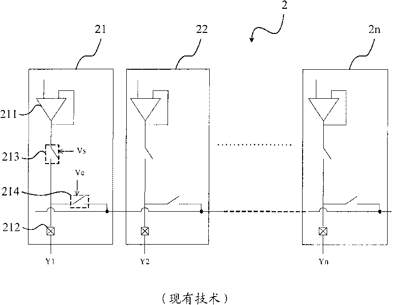
[0010] However, in this driving mode, the gate signals of the driving switch and the charge sharing switch do not change in a linear manner, but change more gently in the sections before and after the rising / falling edge, but still change very quickly in the middle section, The equivalent resistance of the driving switch and the charge sharing switch changes drastically, so a considerable instantaneous current will be generated at this time, as shown in Figure 4(A) and Figure 4(B) respectively
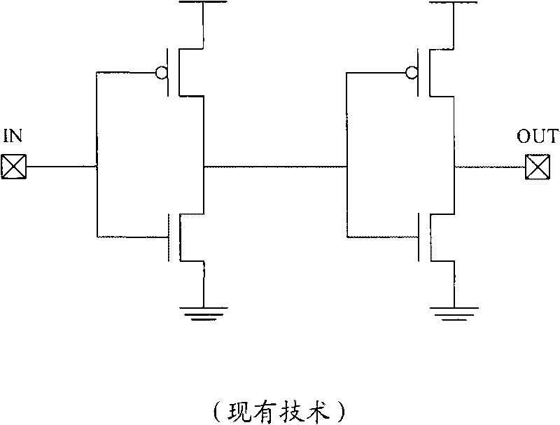
[0011] In addition, even if the driving capability of the logic buffer is reduced to increase the rise / fall time of the gate signal driving the switch and the charge sharing switch, it can only make the changes in the front and rear sections of the rising / falling edge more moderate, but the middle section The change is still very fast, as shown in Figure 4(C)
Therefore, although the instantaneous current has decreased, it is still unable to effectively avoid the occurrence of electromagnetic interference.

Method used


Image

  • Source driving device
  • Source driving device
  • Source driving device

Examples


Embodiment Construction

[0042] The invention provides a source driving device. When the source drive device is used to drive a thin film transistor liquid crystal panel, it can effectively reduce the large instantaneous current generated by the traditional source drive device, and reduce the electromagnetic interference caused by the instantaneous current, so as to ensure that the thin film transistor liquid crystal display The panel is functioning normally.

[0043] Next, the idea and principle of the source driver proposed by the present invention will be briefly introduced. Generally speaking, the performance of the source driver is mainly related to the driving capability of the output buffer, the equivalent resistance value of the driving switch and the charge sharing switch, and the RC load on the panel. Assuming that the driving capability of the output buffer and the RC load on the panel are fixed, the performance of the source driver is mainly affected by the equivalent resistance values ​​...


PUM


Abstract

The invention discloses a source driving device. The source driving device comprises a plurality of channels and a control module. Each of the channels comprises an output buffer, an output cushion, a driving switch and a charge sharing switch. The control module is used for controlling gate signals of the driving switch or the charge sharing switch in each channel to represent linear change. Therefore, the instantaneous current produced by the source driving device can be reduced so as to reduce the occurrence of electromagnetic interference phenomenon.

Description

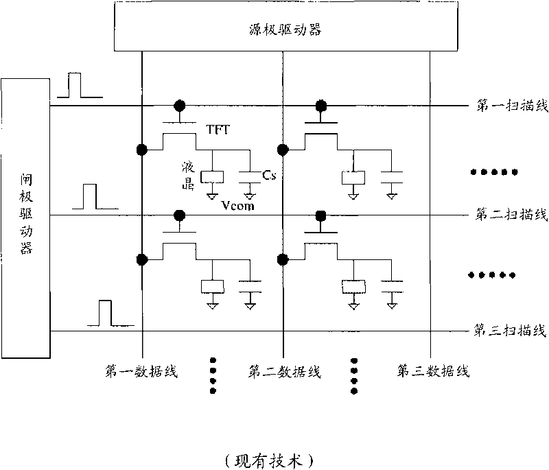
technical field [0001] The present invention relates to a liquid crystal display, and in particular, the present invention relates to a source driving device applied to a thin film transistor liquid crystal display. Background technique [0002] In recent years, due to continuous innovation and advancement of display technologies, various types of display devices, such as liquid crystal displays and plasma displays, have appeared on the market. Since the volume of a liquid crystal display is far smaller than that of a traditional CRT (cathode ray tube, cathode ray tube) display, for modern people who have a small living space, it is indeed more convenient to use a liquid crystal display that takes up less desktop space. [0003] For a general thin film transistor liquid crystal (TFT-LCD) display, its driving device mainly includes two parts: a source driver (source driver or data driver) and a gate driver (gate driver or scan driver). Please refer to figure 1 , figure 1 A...

Claims


Application Information

Patent Timeline
IPC IPC(8): G09G3/36G09G3/20
Inventor 陈怡成梁彦雄赵晋杰苗惠雯左克扬
Owner RAYDIUM SEMICON
Learn More