Distributed traffic signal lamp control system

A traffic signal light and control system technology, which is applied in the field of decentralized traffic signal light control systems, can solve the problems of high pipeline requirements, increase the number of cables used, and heavy workload, so as to achieve high system stability, reduce material costs, and reduce the number of uses Effect

Inactive Publication Date: 2010-06-16
ZHONGSHAN KESHUN ANALYTICAL & TESTING TECH
View PDF0 Cites 14 Cited by
  • Summary
  • Abstract
  • Description
  • Claims
  • Application Information

AI Technical Summary

Problems solved by technology

[0003] 1. The 220V voltage control signal is directly transmitted, which has high requirements on the pipeline. The pipeline needs to be embedded in the early stage of installation, which is difficult and expensive to construct.
For the road surface without pipelines in the early stage, it is necessary to break the road construction, and there is a problem that the construction is relatively difficult, resulting in an increase in construction costs
[0004] 2. The 220V voltage control signal is directly transmitted through the underground, causing safety hazards in other related road constructions
[0005] 3. Since the control of each line is directly issued by the master controller, the number of cables used is increased, and the cost of materials is high. At the same time, the power consumption of the master controller is high, the heat is large, and it is prone to failure
[0006] 4. Since each line is directly controlled by the master controller, when installing and debugging traffic lights, it is necessary to align and number each signal line on the line, the debugging process is cumbersome and the workload is heavy

Method used


Image

  • Distributed traffic signal lamp control system
  • Distributed traffic signal lamp control system
  • Distributed traffic signal lamp control system

Examples


Embodiment Construction

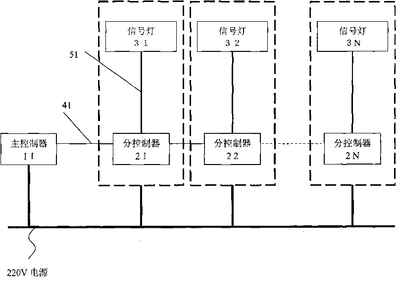
[0041] like figure 1 Shown is the block diagram of the working principle of the decentralized traffic signal light control system. The distributed traffic signal light control system of the present invention includes a main controller 11, several sub-controllers 21, 22, ... 2N and several groups of signal lights 31, 32 ... 3N for indicating traffic signals. Signals and operating parameters are transmitted between the main controller and the sub-controllers, and between the sub-controllers through the network cable 41 , and the sub-controllers control the signal lamp display through the cable 51 . The main controller is not only used to set the operating parameters of all sub-controllers, but also to send synchronous control signals to all sub-controllers. Each sub-controller is connected to a group of signal lights through a two-core 1 square cable to control The display of the set of semaphores.

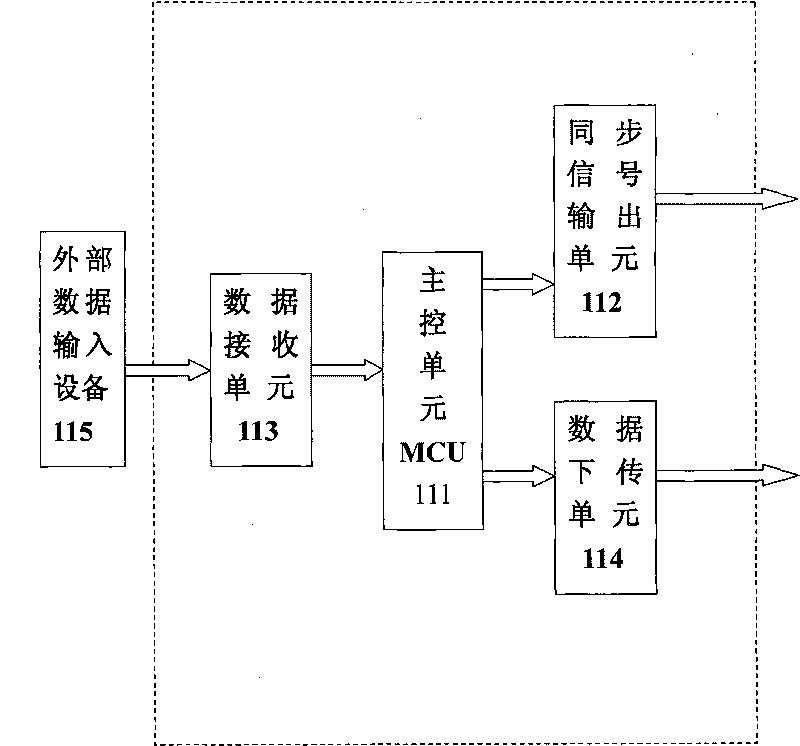
[0042] like figure 2 Shown is the block diagram of the working principle of...


PUM


Abstract

The invention discloses a distributed traffic signal lamp control system, comprising a master controller, a plurality of groups of signal lamps, and a plurality of slave controllers, wherein each slave controller is composed of a data receiving unit, an MCU processor and output control end; the data receiving unit is used for communicating with the master controller in a one-way manner and receiving the signals from the master controller; the MCU processor is used for receiving the data afferent from the data receiving unit, computing according to the preset program and sending an order to the output control end; and the output control end is used for receiving the order from the MCU processor and sending the order to the signal lamps or synchronized slave controllers to control the working state of the signal lamp group or realize data communication among synchronized slave controllers. The invention uses network cable transmission to control signals both in the master controller and the slave controllers, thus reducing the usage amount of cables, lowering material cost, needing no large-scale road breaking when pipelines are not pre-buried and lowering construction cost.

Description

technical field [0001] The invention relates to a traffic signal lamp control system, in particular to a distributed traffic signal lamp control system. Background technique [0002] With the rapid development of the country's economy and the continuous improvement of people's living standards, the number of cars has increased rapidly, resulting in increasing pressure on urban traffic. Traffic problems have become a "bottleneck" that restricts urban development. The existing road traffic light control system A centralized controller is adopted, that is, the traffic lights at each intersection are controlled by a 220V voltage source, and the cables are connected to the general controller installed at a certain intersection, and are controlled by the control signal sent by the general controller. Such a control system structure Has the following defects: [0003] 1. The 220V voltage control signal is directly transmitted, which has high requirements on the pipeline. The pipel...

Claims


Application Information

Patent Timeline
Patent Type & Authority Applications(China)
IPC IPC(8): G08G1/07
Inventor 王耀青
Owner ZHONGSHAN KESHUN ANALYTICAL & TESTING TECH
Why Eureka
Try Eureka