Flywheel simulator with fault simulating function and realizing method
A fault simulation and simulator technology, applied in simulators, instruments, computer control, etc., can solve the problem that the flywheel simulator does not support the fault simulation function.
- Summary
- Abstract
- Description
- Claims
- Application Information
AI Technical Summary
Problems solved by technology
Method used
Image
Examples
specific Embodiment approach 1
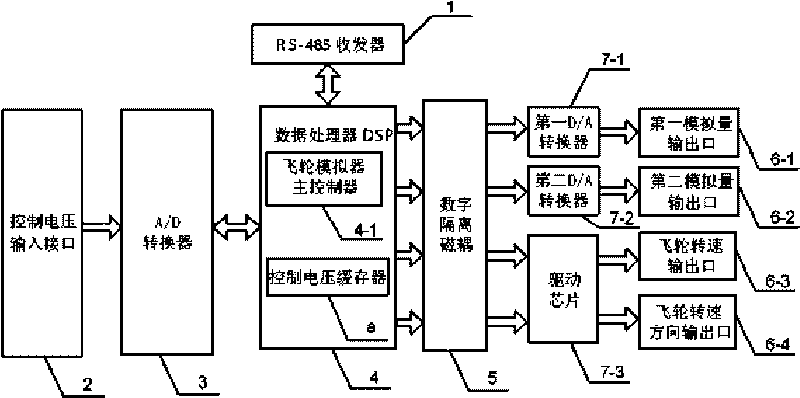
[0016] Specific implementation mode 1. Combination figure 1 Describe this embodiment, the flywheel simulator with fault simulation function, it consists of RS-485 transceiver 1, control voltage input interface 2, A / D converter 3, data processor DSP4, digital isolation magnetic coupler 5, the first D / A converter 7-1, second D / A converter 7-2, drive chip 7-3, first analog output port 6-1, second analog output port 6-2, flywheel speed output port 6 -3 and the flywheel speed direction output port 6-4, the serial communication port of the RS-485 transceiver 1 is connected with the RS-485 serial communication port of the data processor DSP4, and the RS-485 transceiver 1 is used for Inject the parameters and fault types of the flywheel simulator, the output terminal of the control voltage input interface 2 is connected to the input terminal of the A / D converter 3, the signal input / output terminal of the A / D converter 3 is connected to the voltage signal input of the data processor D...
specific Embodiment approach 2
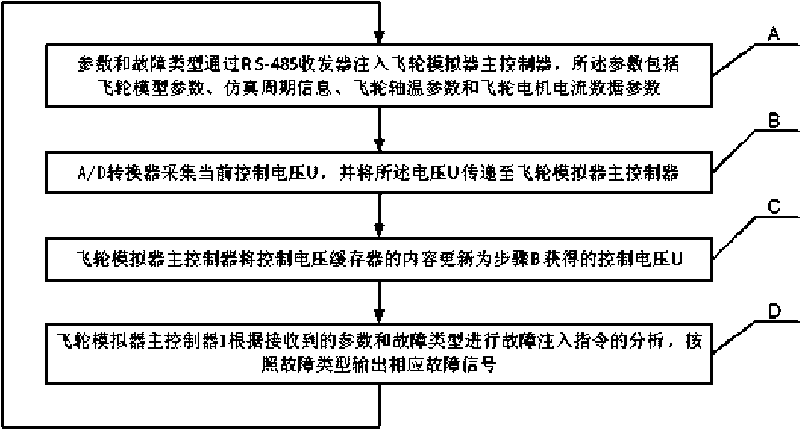
[0018] Specific embodiment two, combine figure 2 Describe this embodiment, this embodiment is to use the simulator described in specific embodiment 1 to realize the method for flywheel fault simulation, each fault simulation is specifically as follows:
[0019] Step A, parameters and fault types are injected into the main controller 4-1 of the flywheel simulator through the RS-485 transceiver 1, and the parameters include flywheel model parameters, simulation cycle information, flywheel shaft temperature parameters and flywheel motor current data parameters;
[0020] Step B, the A / D converter 3 collects the current control voltage U, and transmits the voltage U to the main controller 4-1 of the flywheel simulator;
[0021] Step C, the main controller 4-1 of the flywheel simulator updates the content of the control voltage buffer a to the control voltage U obtained in step B;
[0022] Step D, the main controller 4-1 of the flywheel simulator analyzes the fault injection instr...
specific Embodiment approach 3
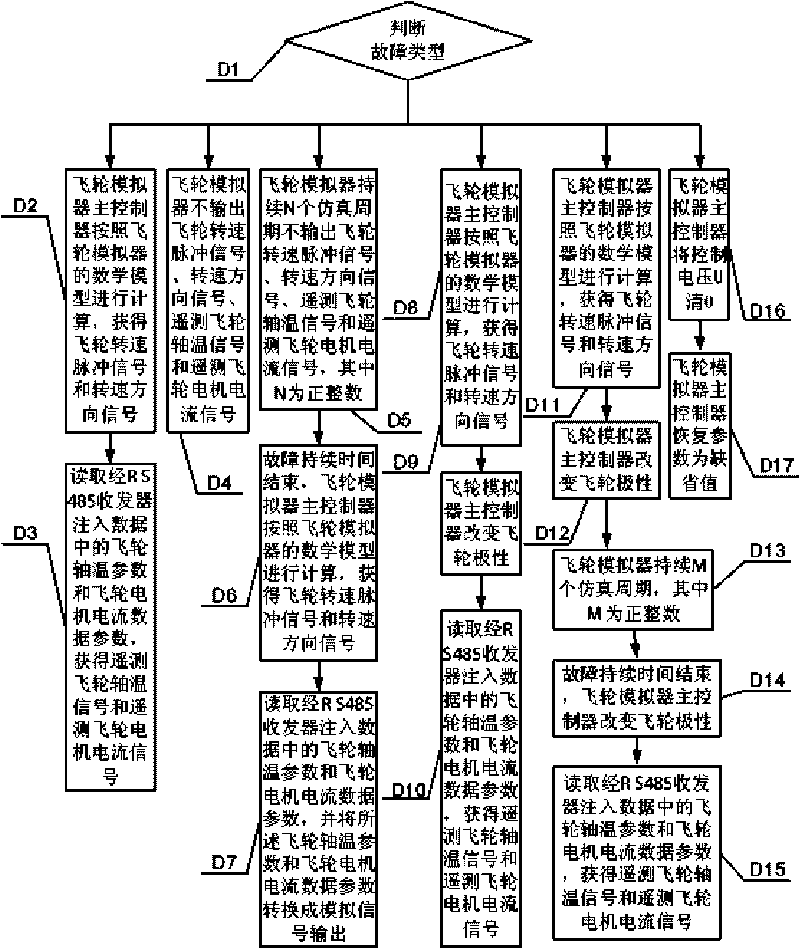
[0026] Specific implementation mode three: combination image 3 Describe this embodiment, this embodiment is a further description of step D:
[0027] Step D1, determine the fault type, if the fault type is 0, then execute step D2, if the fault type is 1, then execute step D4, if the fault type is 2, then execute step D5, if the fault type is 3, then execute step D8, the fault If the fault type is 4, execute step D11; if the fault type is 5, execute step D16;
[0028] Step D2, the main controller 4-1 of the flywheel simulator calculates according to the mathematical model of the flywheel simulator, and obtains the flywheel speed pulse signal and the speed direction signal;
[0029] Step D3, read the flywheel shaft temperature parameter and the flywheel motor current data parameter in the data injected by the RS-485 transceiver 1, obtain the telemetry flywheel shaft temperature signal and the telemetry flywheel motor current signal, and the fault simulation ends;
[0030] Step ...
PUM
 Abstract
Description
Claims
Application Information
 - R&D Engineer
- R&D Manager
- IP Professional
- Industry Leading Data Capabilities
- Powerful AI technology
- Patent DNA Extraction
Browse by: Latest US Patents, China's latest patents, Technical Efficacy Thesaurus, Application Domain, Technology Topic, Popular Technical Reports.
© 2024 PatSnap. All rights reserved.Legal|Privacy policy|Modern Slavery Act Transparency Statement|Sitemap|About US| Contact US: help@patsnap.com


