Automatic switching cylinder manifold device

An automatic switching and busbar technology, applied in the container discharge method, container filling method, pipeline system, etc., can solve the problems of insensitive switching, unstable output gas, and impure output gas, so as to reduce the intensity of manual operation , Stable gas output, sensitive switching effects

Inactive Publication Date: 2010-06-16
丹阳市方蓝气体设备有限公司
View PDF0 Cites 7 Cited by
  • Summary
  • Abstract
  • Description
  • Claims
  • Application Information

AI Technical Summary

Problems solved by technology

However, the existing automatic switching busbar device is firstly that its switching is not very sensitive, there are errors, and often requires manual assistance; secondly, the output gas is impure and has impurities; thirdly, the output gas is unstable

Method used


Image

  • Automatic switching cylinder manifold device
  • Automatic switching cylinder manifold device

Examples


Embodiment 1

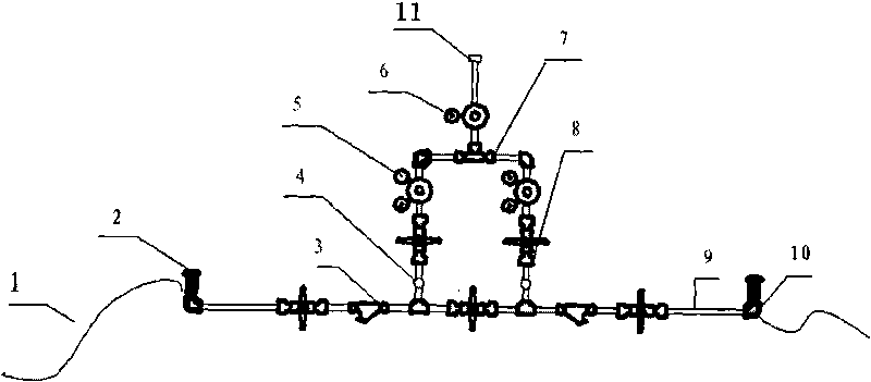
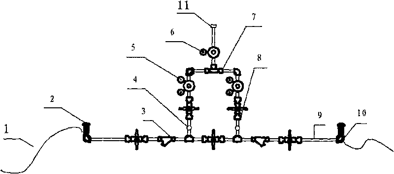
[0012] The structure of this embodiment is as figure 1 As shown, an automatic switching busbar device, its main structure is composed of air intake and air outlet, the air inlet end is connected to the external air source through a high-pressure hose 1, the air outlet end is connected to the pipeline interface 11 through a shuttle valve switching valve 7, and The connection between the high-pressure hose 1 and the shuttle valve switching valve 7 is connected through a high-pressure pipeline 9, and the high-pressure hose 1 and the high-pressure pipeline 9 are arranged in double sets on both sides of the shuttle valve switching valve 7. Safety, the high-pressure hose 1 communicates with the high-pressure pipeline 9 through the pipeline angle valve 2, tee and elbow 10, and the high-pressure pipeline 9 is also equipped with a filter 3 and a first-stage decompression before connecting with the shuttle valve switching valve 7 device 5, and high-pressure cut-off valve 8, and the inst...

Embodiment 2

[0014] It is the same as the automatic switching busbar device of Embodiment 1, the difference is that: between the above-mentioned filter 3 and the second high-pressure cut-off valve 8, an alarm device interface 4 is also installed, and an alarm device is reserved here. The device interface can realize real-time monitoring of remote pressure, gas quality, temperature, bottle change and other work requirements.

Embodiment 3

[0016] The same as the automatic switching busbar device in Embodiment 1, the difference is that a secondary pressure reducer 6 is installed between the above-mentioned shuttle valve switching valve 7 and the pipeline interface 11 to make the output gas more stable.


PUM


Abstract

The invention relates to an automatic switching cylinder manifold device. The device mainly comprises a gas inlet end and a gas outlet end, wherein the gas inlet end is connected with an external gas source through a high-pressure flexible pipe; the gas outlet end is connected with a pipeline joint through a switching valve; the high-pressure flexible pipes are communicated with the switching valve through high-pressure pipelines; two sets of high-pressure flexible pipes and high-pressure pipelines are arranged on the two sides of the switching valve respectively; and a primary decompressor and a high-pressure stop valve are arranged between the high-pressure pipelines and the switching valve. The automatic switching cylinder manifold device is characterized in that: the switching valve is a shuttle valve switching valve. The automatic switching cylinder manifold device has the following advantages that: 1, the shuttle valve switching valve is adopted, so that the automatic switching cylinder manifold device is sensitive to switch, has no error and reduces the operating strength of workers; 2, a filter is added, so that an gas is purer and has no impurity and pollution; 3, a secondary decompressor is added, so that the output gas is more stable; and 4, an alarming device interface is reserved so as to remotely monitor working requirements on pressure, gas quality, temperature, bottle replacement and the like in real time.

Description

technical field [0001] The invention relates to a gas filling device, in particular to an automatic switching bus bar device. technical background [0002] The automatic switching busbar device is a high-efficiency panel control busbar commonly used to transport the gas contained in multiple cylinders to the gas pipeline. In order to ensure automatic switching, it usually consists of the following parts, high-pressure hose, pipeline angle valve, high-pressure pipeline, tee and elbow, pressure reducer, switching valve, high-pressure cut-off valve, using double-sided or bottom air supply, When one side or one side of the gas supply is over, the switching valve will automatically switch to the other side or side, and an alarm will be prompted to replace the gas source in time to ensure continuous work. However, the existing automatic switching busbar device is firstly that its switching is not very sensitive, has errors, and often requires manual assistance; secondly, the outp...

Claims


Application Information

Patent Timeline
IPC IPC(8): F17D3/01F17D1/02F17C13/00
Inventor 王勤修潘小俊朱昌宏
Owner 丹阳市方蓝气体设备有限公司
Why Eureka
Try Eureka