Monostable radial magnetic bearing with low power consumption and zero gravity action

A monostable, zero-gravity technology, applied in the direction of bearings, shafts and bearings, mechanical equipment, etc., can solve the problems of gravity interference, high control response speed, high power consumption, etc., to reduce speed and performance requirements, save System cost, easy assembly and fixation

Inactive Publication Date: 2010-06-16
SHANDONG UNIV OF SCI & TECH
View PDF0 Cites 13 Cited by
  • Summary
  • Abstract
  • Description
  • Claims
  • Application Information

AI Technical Summary

Problems solved by technology

Although the bias magnetic field reduces the excitation current to a certain extent and reduces the power loss, the bias magnetic field generates attractive forces from four directions and cannot offset the gravity of the rotor itself, so it cannot minimize the Small excitation current; and the force between the magnetic fields is inversely proportional to the distance of the air gap between the stator and rotor, and the suction force on the side where the air

Method used


Image

  • Monostable radial magnetic bearing with low power consumption and zero gravity action
  • Monostable radial magnetic bearing with low power consumption and zero gravity action
  • Monostable radial magnetic bearing with low power consumption and zero gravity action

Examples


Embodiment Construction

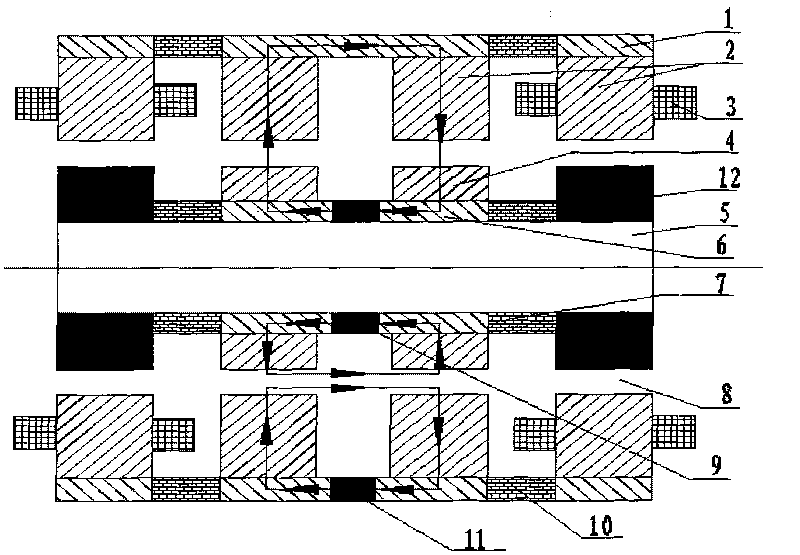
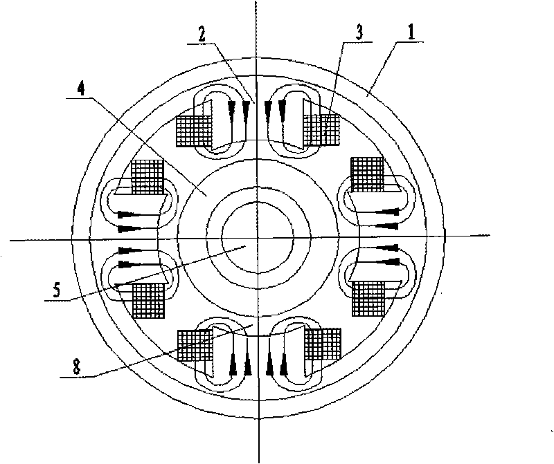
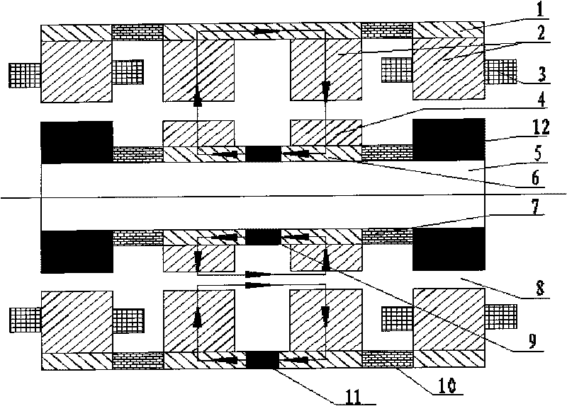
[0009] like figure 1 and figure 2 As shown, it is the basic implementation form of the technical solution of the present invention, which consists of 5 outer magnetic rings 1 (2 circular rings and 3 semi-circular rings), 1 axially magnetized inner permanent magnetic ring 9, and 1 axially magnetized Outer permanent magnet half ring 11, 2 radially magnetized inner permanent magnet rings 12, 12 stator cores 2 (8 columns and 4 semicircular rings), 8 excitation coils 3, 2 inner magnetic rings 6, 2 It consists of 4 rotor core rings, 12 air gaps 8, 2 inner magnetic isolation rings 7, 2 outer magnetic isolation rings 10, and 1 rotating shaft 5. Each stator core 2 includes 4 electromagnetic poles and 2 permanent magnet poles in the positive and negative directions of the X-axis and Y-axis. The stator cores at the left and right ends form 8 electromagnetic poles and 4 permanent magnet poles in total. The magnetic pole is wound with an excitation coil 3, and the outside of the stator ...


PUM


Abstract

The invention relates to a monostable radial magnetic bearing with low power consumption and a zero gravity action, which belongs to the field of magnetic suspension bearings and comprises an outer magnetic conduction ring, an outer magnetic isolation ring, an iron core of a stator, an excitation coil, an inner permanent magnetism ring with axial magnetization, an iron core of a rotor, an inner magnetic isolation ring, an inner magnetic conduction ring, inner permanent magnetism rings with radial magnetization, an outer permanent magnetism semiring with axial magnetization, an air gap and a rotor shaft. The iron core of the stator comprises electromagnetic iron cores and permanent-magnetism iron core rings, which form total eight electromagnetic poles at the left end and the right end of the bearing and four semicircular ring type permanent magnetism poles together, wherein the two upper semicircular rings generate attractive force, and the two lower semicircular rings generate repulsive force. In the negative direction of the Y axis of the stator, the outer permanent magnetism semiring with axial magnetization is clamped between the two permanent-magnetism iron core rings of the stator by the outer magnetic conduction ring, the inside of the iron core of the stator is provided with the iron core of the rotor and the inner permanent magnetism rings with radial magnetization, the iron core of the rotor is positioned in the middle, the inner permanent magnetism rings with radial magnetization are positioned at both ends, the middle of the inner magnetic conduction ring is clamped with the inner permanent magnetism ring with axial magnetization, and the air gap is arranged between the inner surface of the stator and the outer surface of the rotor.

Description

Technical field [0001] The patent of the invention belongs to the field of non-contact magnetic suspension bearings. It is a low-power monostable zero-gravity radial magnetic bearing, which can replace the current contact mechanical bearings and can be used as wind power generators, motors, molecular pumps, and high-speed bearings. , Non-contact support components for rotating equipment such as rotor dynamics verification and testing, vibration isolation, etc. Background technique [0002] At present, the pure permanent magnet magnetic suspension bearing is unstable and uncontrolled; the pure electromagnetic magnetic suspension bearing consumes a lot of current and consumes a lot of power; the permanent magnetic and electromagnetic hybrid magnetic suspension bearing is the most widely studied, and its significant The characteristic is: using a permanent magnet to generate a bias magnetic field, the bias magnetic field generates equal and large attractive forces on the magnet...

Claims


Application Information

Patent Timeline
IPC IPC(8): F16C32/04
Inventor 肖林京孙传余李鹏武洪恩
Owner SHANDONG UNIV OF SCI & TECH
Why Eureka
Try Eureka