Valve tappet device of engine

A technology of engine valve and rod device, applied in the direction of engine components, machine/engine, valve device, etc., can solve the problems of flexibility and rotation direction, affecting the service life of the tappet, increasing the stress on the edge of the pin, etc. And the effect of good transmission, convenient assembly, and reduced contact stress

Active Publication Date: 2010-06-16
WUXI XIZHOU MACHINERY
View PDF0 Cites 3 Cited by
  • Summary
  • Abstract
  • Description
  • Claims
  • Application Information

AI Technical Summary

Problems solved by technology

[0002] Before the present invention is made, in the existing technology, the valve tappet device of the engine is usually connected with the valve guide by using the valve tappet and is designed to be in contact with the rollers, which often leads to heavy wear of the rollers and a low service life , the flexibility and the direction of rotation are relatively greatly affected; at the same time, in order to prevent the axial movement of the roller pin, the existing tappet adopts interference assembly between the roller pin and the tappet body. In order to meet the performance requirements, people often use Freezing assembly or forcing the pin into the pin hole on the tappet often results in increased stress on the edge of the pin, resulting in high assembly costs and unsatisfactory performance
Thereby seriously affecting the service life of the whole tappet body

Method used


Image

  • Valve tappet device of engine
  • Valve tappet device of engine
  • Valve tappet device of engine

Examples


Embodiment Construction

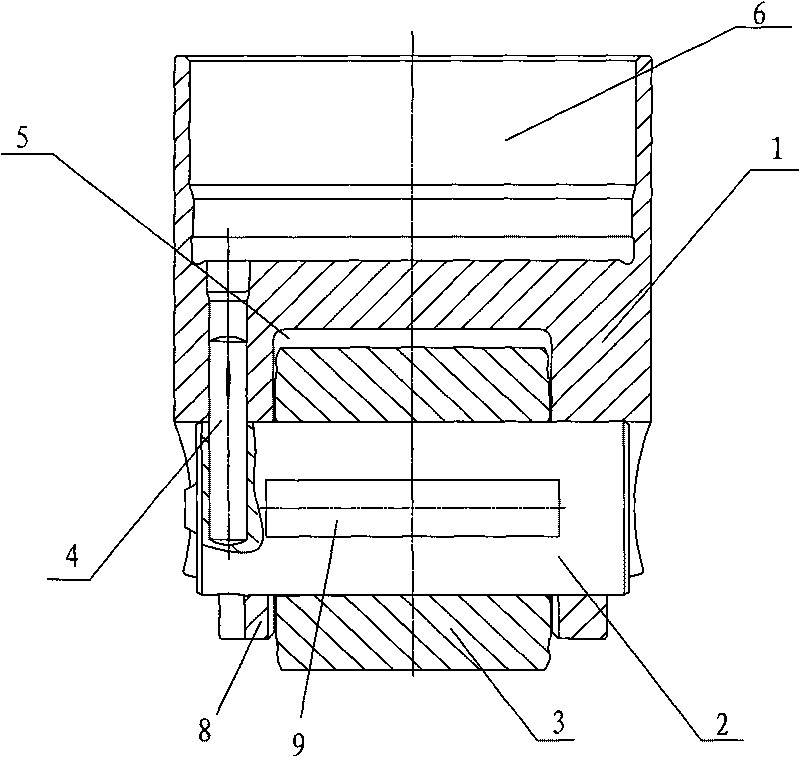
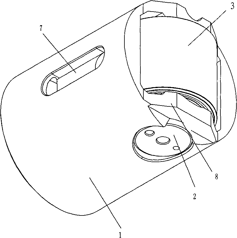
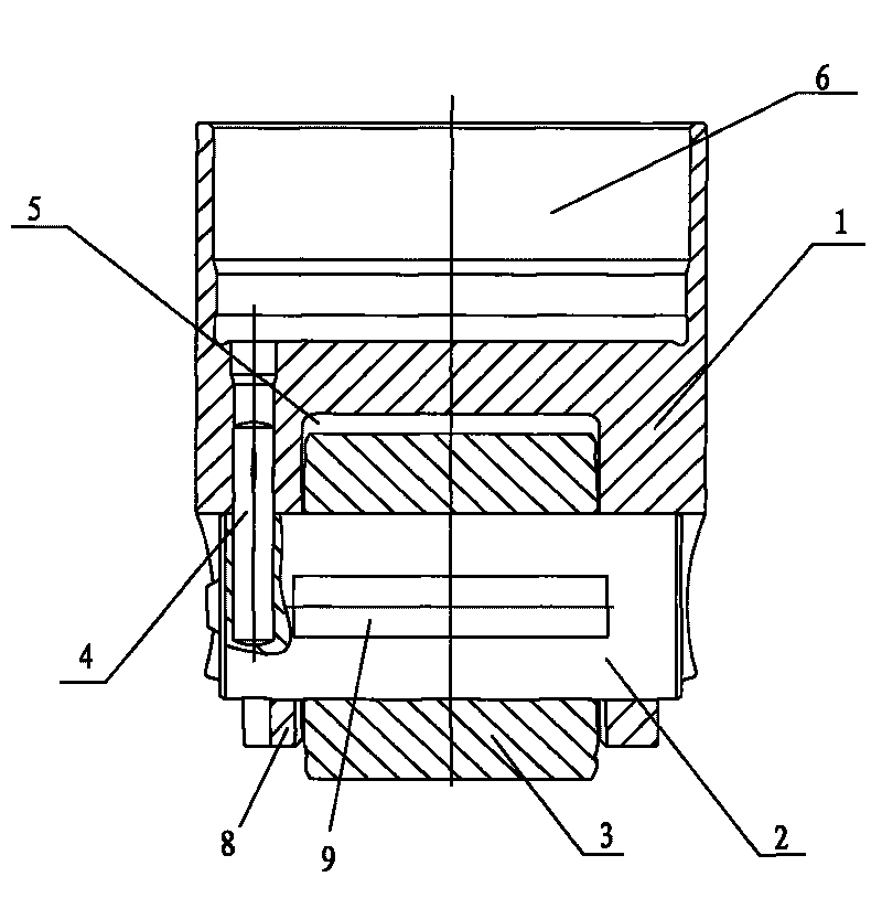
[0009] like figure 1 As shown: the side axial U-shaped positioning groove 7 of the tappet body 1, the two side wings of the tappet body are provided with through holes that are concentric and perpendicular to the axis of the tappet body 1; the two sides of the roller pin 2 The ends are respectively located in the through holes of the two side wings; the roller pin 2 is provided with a roller 3, and the roller 3 is located in the roller groove opened by the tappet body. The roller pin 2 and the tappet body 1 are fixed by a positioning pin 4 . The roller pin 2 and the tappet body 1 are clearance fit, and the positioning pin 4 limits the axial movement of the roller pin 2, thus ensuring the reliability of the roller pin 2 in use. Described roller 3 is installed on the roller pin 2, and roller 3 can rotate in the positioning groove 5 of tappet body 1, and roller 3 and roller pin 2 are clearance fit, and roller 3 can slide on roller pin 2. The positioning pin 4 is located at one ...


PUM


Abstract

The invention relates to a valve tappet device of an engine, which belongs to the technical field of mechanical structures. According to the technical scheme of the invention, the valve tappet device of the engine comprises a tappet body and is characterized in that a positioning groove is formed at the lower end of the tappet body, and concentric through holes which are vertical to the axial line of the tappet body are formed on two side wings forming the positioning groove; two ends of a roller pin are respectively positioned in the through holes of the two side wings; and a roller is arranged on the roller pin, and the roller is positioned in the positioning groove. The valve tappet device removes a bush between the roller and the roller pin, thereby reducing the number of parts, reducing the friction, reducing the cost and facilitating the production. The valve tappet device can increase the diameter and the width of the roller and the roller pin, improve the strength of the roller and the roller pin, reduce the contact stress between the roller and a cam, increase the reliability of a product, arrange an ejector rod slot on the tappet body, effectively increase the contact area between an ejector rod and the tappet body, significantly reduce the edge stress, greatly enhance the performances of abrasion resistance, tension resistance and pressure resistance and effectively prolong the service life of the tappet body.

Description

technical field [0001] The invention relates to an engine valve lifter device, in particular to a gas distribution mechanism applied to a diesel engine, and belongs to the technical field of mechanical structures. Background technique [0002] Before the present invention is made, in the existing technology, the valve tappet device of the engine is usually connected with the valve guide by using the valve tappet and is designed to be in contact with the rollers, which often leads to heavy wear of the rollers and a low service life , the flexibility and the direction of rotation are relatively greatly affected; at the same time, in order to prevent the axial movement of the roller pin, the existing tappet adopts interference assembly between the roller pin and the tappet body. In order to meet the performance requirements, people often use Freezing assembly or forcing the pin into the pin hole on the tappet body often results in increased stress at the edge of the pin, result...

Claims


Application Information

Patent Timeline
Patent Type & Authority Applications(China)
IPC IPC(8): F01L1/16
Inventor 包建忠
Owner WUXI XIZHOU MACHINERY
Why Eureka
Try Eureka