


Quick Research
Generate reliable direction feasibility study reports for your R&D in just a few steps.

Technical Q&A
Discover and master advanced knowledge NOW. Basics, ideas, possibilities, all at once.

Find Solutions
As an expert in R&D theories, this can generate solutions to your technical problems instantly.

Evaluate Feasibility
Analyze your overall solution with one click, know your potential R&D risks in advance.

Monitor Landscape
Get weekly tech updates, stay abreast of the latest tech innovations and key insights.
Sliding automobile luggage rack/case
A car luggage rack, sliding technology, applied in vehicle parts, additional accessories, transportation and packaging, etc., can solve the problems of increased use space, low use efficiency, and inability to play, to meet utilization, ensure stability and Safety, flexible loading and unloading effects
- Summary
- Abstract
- Description
- Claims
- Application Information
AI Technical Summary
Problems solved by technology
Method used
Image


Examples
Embodiment 1
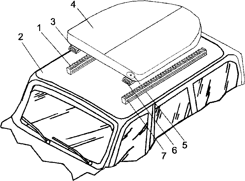
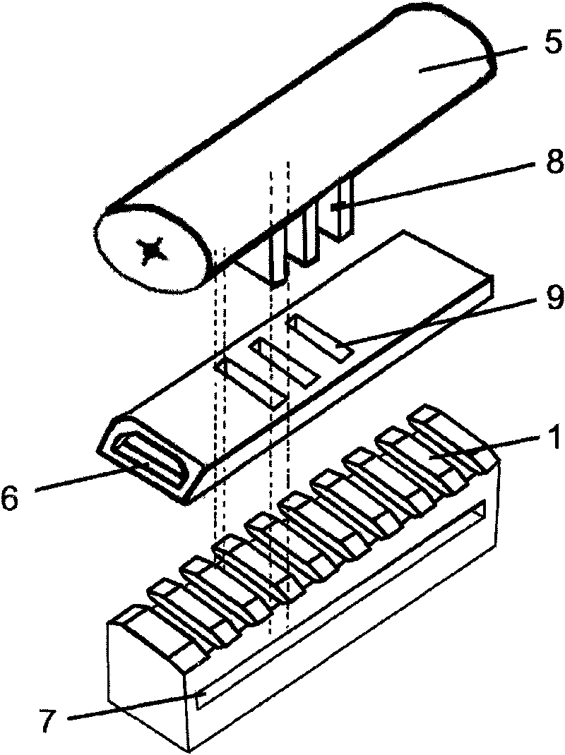
[0020] Depend on figure 1 , figure 2 A sliding car luggage rack / case shown includes a toothed fixed guide rail 1, and a sliding part 3 with a luggage case 4 installed on the fixed guide rail 1, which is also called a Picatinny guide rail mechanism. The luggage case 4 is provided with a positioning lock 5 , and the positioning lock 5 passes through the positioning locking hole 9 on the sliding part 3 through the locking tongue 8 thereon and is inserted into the tooth space of the tooth-shaped fixed guide rail 1 . In this way, the positioning of the luggage case 4 and the stay at any position are controlled by the positioning lock 5, which facilitates loading and unloading of the luggage case 4. In addition, considering the ease of use of the suitcase 4, and the through-pin shaft 6 provided at the front end of the sliding part 3 is fitted with the sliding hole 7 on the fixed guide rail 1, so that the sliding part 3 on the suitcase 4 slides to When the final end of the guide r...
Embodiment 2
[0026] Depend on image 3 given with figure 1 Connectors of different structures. it is in figure 1 On the basis of this, a corresponding improvement is made, that is, the connecting body is provided with a ball stud shaft 16 on one lateral side of the sliding part 3; One end of the ball stud shaft 16 passes through the sliding hole 17 of the fixed guide rail 1 and is connected to the side of the sliding part 3; while the ball head of the ball stud shaft 16 is located on the side of the fixed guide rail 1 to ensure the connection between the two bodies , to achieve horizontal displacement and rotation functions.
Embodiment 3
[0028] Figure 4 is a combination figure 1 The rear auxiliary frame is added on the basis of the structure. A right-angled auxiliary frame 10 is hinged on the sliding part 3 of the luggage case 4 . Under normal circumstances, the auxiliary rack 10 is turned over on the luggage case 4 to form an upward vertical body, which acts as a barrier to limit the serial movement of articles; The frame 10 is in a right angle state with the luggage rack downwards, so that the luggage case 4 in the inclined position is supported on the vehicle body by the auxiliary frame 10 to ensure the stability of the luggage case.
[0029] The auxiliary rack 10 of this embodiment can also be installed and matched in a telescopic manner in addition to the installation method of connecting the above luggage rack / box with a pin shaft. When the auxiliary frame 10 and the sliding part 3 are installed in a telescopic manner, the difference is that the vertical body of the right-angled auxiliary frame 10 fa...
PUM
 Abstract
Description
Claims
Application Information
 - R&D Engineer
- R&D Manager
- IP Professional
- Industry Leading Data Capabilities
- Powerful AI technology
- Patent DNA Extraction
Browse by: Latest US Patents, China's latest patents, Technical Efficacy Thesaurus, Application Domain, Technology Topic, Popular Technical Reports.
© 2024 PatSnap. All rights reserved.Legal|Privacy policy|Modern Slavery Act Transparency Statement|Sitemap|About US| Contact US: help@patsnap.com