
Device for cutting section mould plate

A cutting device and template technology, applied in welding equipment, gas flame welding equipment, metal processing equipment, etc., can solve problems such as inability to accurately cut plates, and achieve the effect of ensuring construction period and quality and saving investment.

Active Publication Date: 2013-02-27
CHINA RAILWAY NO 3 GRP CO LTD
View PDF0 Cites 0 Cited by
  • Summary
  • Abstract
  • Description
  • Claims
  • Application Information

AI Technical Summary

Problems solved by technology

[0003] The present invention aims at the deficiencies in the above-mentioned prior art, and designs a formwork cutting device. The present invention also discloses a method for cutting arc lines on plates by using the formwork cutting device, which solves the problem of making large-scale steel formwork at the construction site. The problem that the plate cannot be cut accurately

Method used


Image

  • Device for cutting section mould plate

Examples


Embodiment Construction

[0011] The present invention will be described in detail below in conjunction with the accompanying drawings.

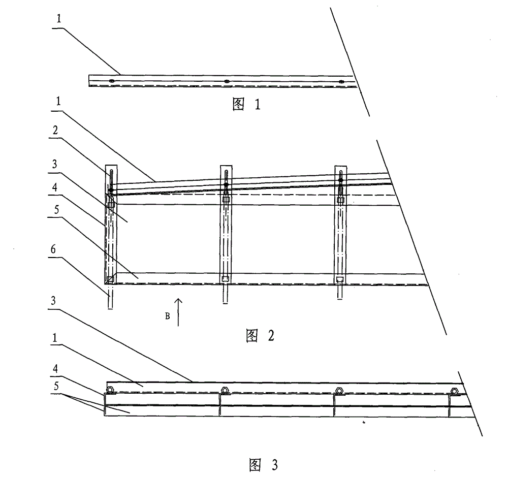
[0012] refer to Figure 2-3 A type of formwork cutting device of the present invention has a track base 5, which is composed of two parallel angle steels or channel steels, and a steel plate can also be directly used as the track base, and on the track base every 0.5 meters to 1 Fix a leading screw seat 4, this leading screw seat 4 can adopt angle steel or channel steel, leading screw seat and rail base 5 are welded or bolted or adopt other ways to fix. One end of the screw seat 4 is formed with a strip-shaped fixing hole 2, and a fastening bolt is pierced in the hole. There is a fixing hole on the track 1 corresponding to the screw seat 4, and the track 1 is connected to the screw seat 4 by bolts. , the track 1 is made of angle steel or I-beam or other structural materials. The other side of the leading screw seat has an adjusting leading screw 6, and the inner ...


PUM


Abstract

The invention provides a device for cutting a section mould plate, comprising a rail for a cutting machine to travel and a rail base, wherein the rail base is provided with a screw seat at 0.5-1m intervals; the screw seat is provided with a regulating screw and a strip-shaped fixed hole; the strip-shaped fixed hole is internally provided with a fastening bolt; and the rail is connected with the screw seat by the fastening bolt. The device for cutting the section mould plate in the invention mainly uses several angle irons to prepare into a simple rail device, and section mould plates with smooth curves and small errors can be obtained by cutting via the cutting device, thus solving the key technology for manufacturing the section mould plate on site, providing conditions for preparing standard type templates for large-scale piers, saving investment greatly and ensuring the progress and quality.

Description

technical field [0001] The invention relates to a track device for a plate cutting machine, specifically a formwork cutting device matched with a cutting machine that can cut a large plate into arc-shaped edges. The method of cutting arc lines. Background technique [0002] At present, various large or super large concrete pier projects are often encountered in the construction of railways, highways and other projects. Many piers are designed with a conical end shape, that is, the cross-section of the pier gradually becomes smaller from the bottom to the top, and the cross-section of the pier is straight on both sides and arc-shaped at both ends. Under the existing technical conditions, the construction of this bridge pier is to make the steel formwork first, then the steel formwork is assembled and welded on site and then cast. The usual practice is to make steel formwork with special equipment at the base and then transport it to the site for assembly. Since the construc...

Claims


Application Information

Patent Timeline
Patent Type & Authority Patents(China)
IPC IPC(8): B23K7/00B23K7/10
Inventor 张振宇张文德孙文友王荣耀任克平王志伟李玉梅王志旭常桂爽范海红
Owner CHINA RAILWAY NO 3 GRP CO LTD
Learn More