
Automatic pistol

A pistol, automatic technology, applied in pistols, firearms, weapon accessories and other directions, can solve the problems of reduced shooting accuracy, complicated firearm design engineering, firearm reliability and shooting accuracy effects, etc., to achieve reliability improvement, design and manufacturing simplification, The effect of improving shooting accuracy

Active Publication Date: 2010-06-09
HANS WRAGE & CO
View PDF0 Cites 5 Cited by
  • Summary
  • Abstract
  • Description
  • Claims
  • Application Information

AI Technical Summary

Problems solved by technology

As a result, the reliability and accuracy of fire of the gun were negatively affected
Firing accuracy is further reduced due to the fact that the locking lugs are placed approximately below the barrel axis and at a maximum distance from the rear end of the barrel, causing displacement of the cartridge case and locking element during discharge of the flame
The action of the bolt carrier and the needles arranged crosswise leads to the transfer of motion from the pneumatic piston to the bolt, which complicates the engineering of the firearm design

Method used


Image

  • Automatic pistol
  • Automatic pistol
  • Automatic pistol

Examples


Embodiment Construction

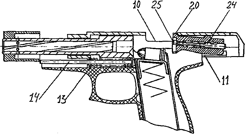
[0017] An automatic pistol comprises a stationary barrel 1 with an end piece 2 arranged in a bolt carrier 3 . The bolt 5 is provided with a guide channel 4 for the end piece. Cylinder 6 surrounds the front of the barrel. The gas chamber is secured to the barrel by a bolted connection (not shown), which simplifies assembly and disassembly of the firearm. Gas conduits 7 are arranged along the length of the barrel. A pneumatic piston 8 is arranged in the cylinder. The extension of the gas piston is designed as a bolt slide / bracket. On the side area of ​​the bolt carrier, a locking curve 9 for controlling the function of the bolt 5, an opening for ejecting the cartridge case 10, and a guide 11 through which the pneumatic piston is arranged in the bolt carrier 3 and move in end piece 2. Guide grooves 12 for the pneumatic piston are provided in the bolt carrier and end piece. Return spring 13 and spring rod 14 are arranged below the gun barrel. The bolt 5 has a recess 15 whic...


PUM


Abstract

The inventive automatic pistol relates to small arms in particular to the structural design of automatic small arms with the powder gas-operated reloading. A barrel (1) is provided with a tail (2) situated in the lower part of a face of breech and is mounted on a frame (3). A bolt (5) is designed in such a way that the front part thereof is tipped up in the extreme front position and, for this purpose, is provided with a tip up support (19). Bolt lugs (21), which are mounted on the front part of the bolt sides, enter the grooves made on the barrel shank when the barrel is closed in such a waythat they are engaged with locking lugs (23) located in the grooves. A spring-loaded gas piston is provided with a spent case ejecting window and is designed in such a way that, when moving back, it releases the bolt lugs (21) and moves the bolt back, and, when moving forward, it moves the bolt forward, a closing lug (20) being in the piston window, and to twist it downward. A gas chamber is mounted on the chase of the barrel in such a way that it encompasses the barrel, gas-discharge channels being made on the barrel circle.

Description

technical field [0001] The invention described here relates to the design and engineering of firearms, particularly automatic firearms, in which the firearm is reloaded by the discharge of explosive-forming gases (pneumatic reloader). Background technique [0002] The Carbine S (the GDR variant of the SKS-45 Simonov Automatic Carbine) was a self-loading firearm whose main components consisted of a fixed barrel with gas discharge and a bolt case with locking lugs , The gas discharge device consists of a cylinder, a gas pipe, a pneumatic piston and a spring-loaded gas rod. The bolt of a self-loading firearm consists of a bolt safety carrier and a locking element with a guide edge. By pulling the rear end of the locking element behind the locking lug of the bolt housing, the bolt is closed ("Instructions for the Operation of Firearms (наставление по стрелковомуделу)", Publishing House of the Military Division of the USSR Ministry of Defense, Moscow, 1973, pp. 180-188 Page). ...

Claims


Application Information

Patent Timeline
Patent Type & Authority Applications(China)
IPC IPC(8): F41A5/20F41C3/00
CPCF41A5/26F41A5/20F41C3/00
Inventor V·A·卡明斯基
Owner HANS WRAGE & CO
Learn More