
Whole 'U'-shaped silicon core structure

A silicon core and overall technology, applied in the direction of silicon compounds, inorganic chemistry, non-metallic elements, etc., can solve the problems of poor contact at the lap joint, high resistance, poor quality of polysilicon, and lodging of the silicon core, so as to avoid the lodging of the silicon core, The effect of improving the rate of first-class products and uniform resistance

Inactive Publication Date: 2010-06-09
LUOYANG JINNUO MECHANICAL ENG
View PDF0 Cites 7 Cited by
  • Summary
  • Abstract
  • Description
  • Claims
  • Application Information

AI Technical Summary

Problems solved by technology

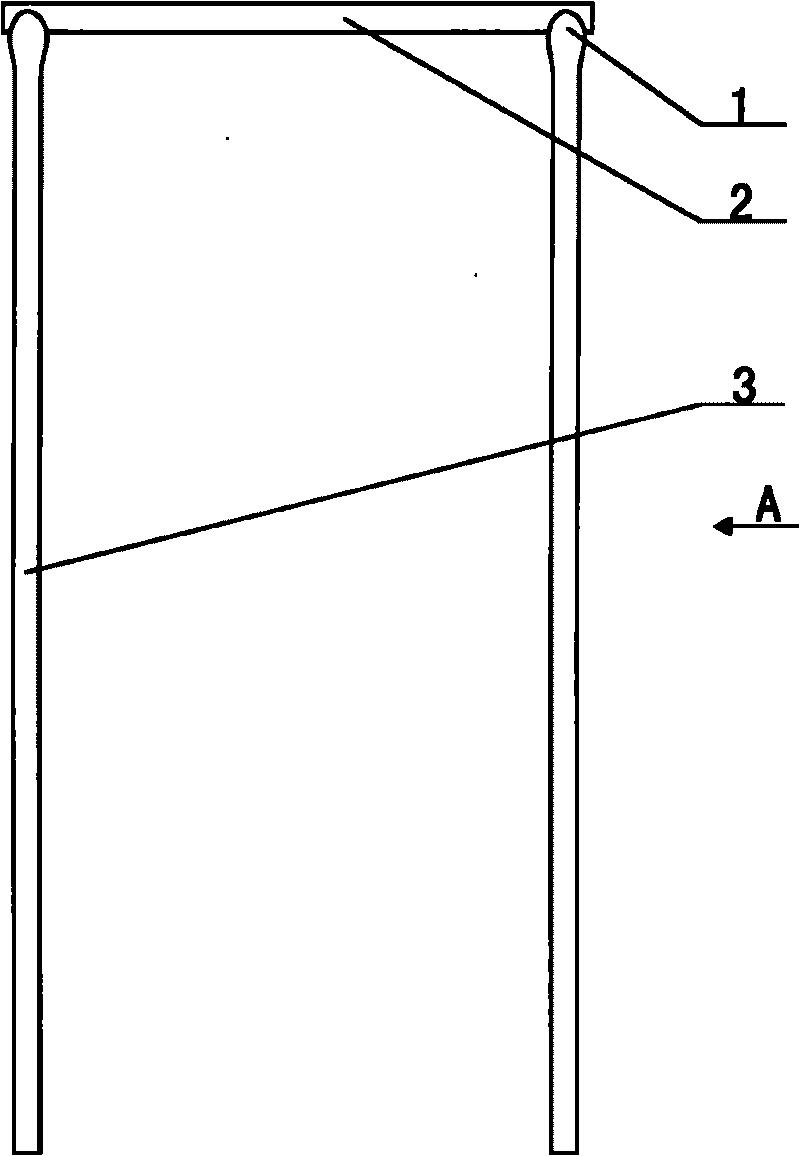
However, no matter which lap joint technology is used, there will be the following two defects: first, the contact surface at the lap joint is too small, resulting in poor contact at the lap joint and high resistance, and the quality of the polysilicon obtained here during the reduction reaction. Poor, the jargon is called "turning material"; second, it can be positioned by the "U" or "V" shaped mouth (4) "or groove" in the front and rear directions, but it cannot be positioned in the left and right directions; thus, in the reduction process It is easy to cause the silicon core to fall

Method used


Image

  • Whole 'U'-shaped silicon core structure
  • Whole 'U'-shaped silicon core structure
  • Whole 'U'-shaped silicon core structure

Examples


Embodiment Construction

[0018] The present invention can be explained in more detail with reference to the following examples; however, the present invention is not limited to these examples.

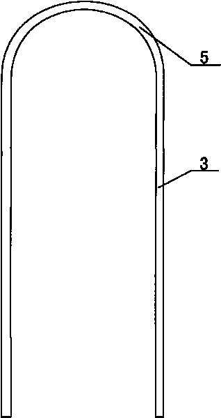
[0019] combined with Figure 2-6 The overall "U"-shaped silicon core structure, including the silicon core body, is image 3 The middle part of the structure silicon core that the present invention provides is circular arc 5 shape, and two vertical silicon cores 3 are respectively connected with the two ends of circular arc 5; Figure 4 The structure provided by the present invention is two circular arcs 5, and a straight connection silicon core 6 is arranged between the circular arcs 5 and 5 for connection, and the two vertical silicon cores 3 are respectively connected to the outer ends of the two circular arcs 5; combine Figure 5 The structure provided by the present invention is that two directly connected silicon cores 6 are connected with three circular arcs 5 to form a bending section of the silicon ...


PUM


Abstract

The invention relates to a silicon core structure, in particular to a whole 'U'-shaped silicon core structure which comprises a silicon core body; the middle part of a silicon core is provided with a circular arc (5) or at least two circular arcs (5), and a straight connecting silicon core (6) is arranged between every two circular arcs (5) for connection; two vertical silicon cores (3) are respectively connected with one end of the two circular arcs (5) arranged at the outmost periphery, so as to form the whole 'U'-shaped silicon core structure. As no interface is arranged in the whole 'U'-shaped silicon core structure, the running resistance of the whole silicon core of an electrode is more uniform; and more particularly, the phenomenon of silicon core lodging caused in the production process can be effectively avoided. Furthermore, the silicon core structure reduces the complexity of design and manufacturing of a reduction furnace, thus not needing high-voltage breakdown and reducing the unit power consumption of polycrystalline silicon production.

Description

【Technical field】 [0001] The invention relates to a silicon core structure, in particular to an integral "U"-shaped silicon core overlapping structure. 【Background technique】 [0002] At present, it is known that in the process of producing polysilicon by the Siemens method, silicon core lapping technology is used for ordinary wafers, which is mainly used in a link of polysilicon production, that is, the reduction reaction process. The working principle of the reduction reaction process is that polysilicon is placed in a closed reduction furnace, combined with figure 1 or figure 2 Before the furnace is installed, several closed loops are lapped with silicon cores in the reduction furnace, also called "bridges". Each closed loop is composed of two vertical silicon cores (3) and one horizontal silicon core (2). The two vertical silicon cores (3) of each closed circuit are respectively connected on two electrodes on the bottom of the furnace, and the electrodes are connected...

Claims


Application Information

Patent Timeline
Patent Type & Authority Applications(China)
IPC IPC(8): C01B33/035
Inventor 刘朝轩王晨光史优才陈海廷
Owner LUOYANG JINNUO MECHANICAL ENG
Learn More