
High-temperature superconducting energy storage flywheel with thermal isolation connection

A high-temperature superconducting and flywheel technology, applied in the direction of control of mechanical energy, magnetic attraction or thrust holding device, electrical components, etc., can solve problems such as difficult heat transmission and superconductor quenching

Inactive Publication Date: 2012-04-11
INST OF ELECTRICAL ENG CHINESE ACAD OF SCI
View PDF1 Cites 4 Cited by
  • Summary
  • Abstract
  • Description
  • Claims
  • Application Information

AI Technical Summary

Problems solved by technology

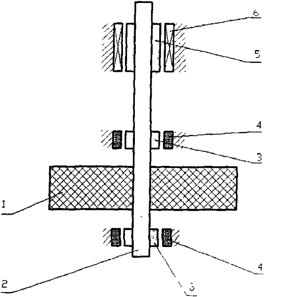
[0005] The purpose of the present invention is to overcome the shortcoming that the heat generated by the motor rotor in the traditional high-temperature superconducting flywheel system is transmitted to the rotor of the high-temperature superconducting magnetic suspension bearing through the rotating shaft, which may cause superconductor quenching. The present invention proposes a motor rotor and superconducting magnetic suspension A rotating shaft with a thermal isolation device installed between the bearing rotors makes it difficult for the heat generated by the motor rotor to be transmitted to the rotor of the high-temperature superconducting magnetic suspension bearing

Method used

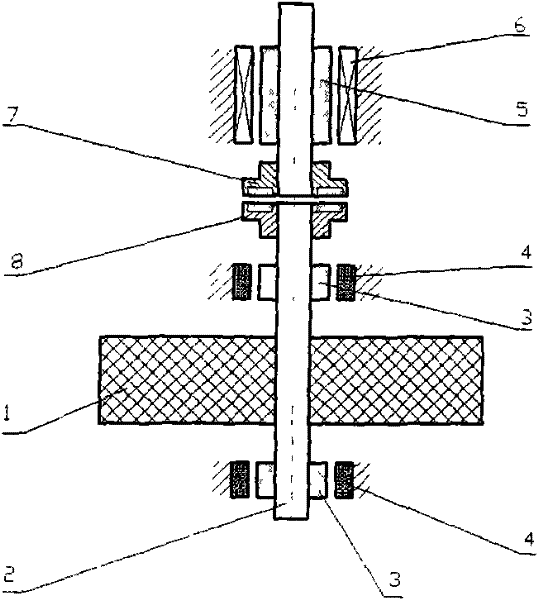
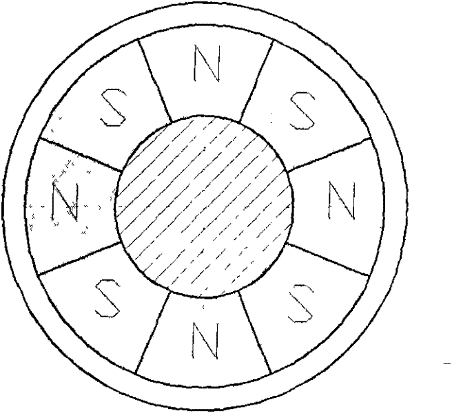

Image

  • High-temperature superconducting energy storage flywheel with thermal isolation connection
  • High-temperature superconducting energy storage flywheel with thermal isolation connection
  • High-temperature superconducting energy storage flywheel with thermal isolation connection

Examples


Embodiment Construction

[0015] The present invention will be further described below in conjunction with the accompanying drawings and specific embodiments.

[0016] Such as figure 2 As shown, the flywheel is composed of a flywheel body 1, a rotating shaft 2, two high-temperature superconducting magnetic suspension bearings (including a permanent magnet rotor 3 and a high-temperature superconducting stator 4), and a motor (including a motor rotor 5 and a stator 6). In the present invention, a permanent magnet coupling device is installed on the rotating shaft 2 of the flywheel system. A permanent magnet coupling device is installed between the motor stator 6 and the high temperature superconducting magnetic suspension bearing 3 of the flywheel system. The permanent magnet coupling device consists of A coupling primary 7 and a coupling secondary 8 are formed, which are arranged on the rotary shaft 2 . The permanent magnet coupling device forms an air-gap magnetic connection between the motor and the...


PUM


Abstract

The invention relates to a high-temperature superconducting energy storage flywheel system with thermal isolation connection, which is characterized in that a permanent magnetic coupling device is arranged between a motor stator (6) and a high-temperature superconducting magnetic suspension bearing (3) of a flywheel system; the permanent magnetic coupling device consists of a primary coupling device (7) and a secondary coupling device (8); the primary coupling device (7) and the secondary coupling device (8) are oppositely distributed on a rotating shaft (2); the permanent magnetic coupling device is used for transferring torque between a motor and a flywheel and meanwhile isolating heat conduction between the motor and the flywheel so as to prevent causing influence on the stability of the high-temperature superconducting magnetic suspension bearing caused by temperature rise of the motor in the operating process of the flywheel system; the coupling device has two forms: a disc form and a cylinder form; and in order to reduce radiation and thermal leakage of the coupling device, the opposite surfaces of the primary coupling device (7) and the secondary coupling device (8) are silvered or pasted with metal thin films.

Description

technical field [0001] The invention relates to a high-temperature superconducting energy storage flywheel device. Background technique [0002] The development and utilization of green and renewable energy is the top priority in the field of energy engineering research in various countries at present, to reduce the proportion of fossil fuel consumption, protect the environment and improve efficiency. However, compared with traditional coal-fired and oil-fired power generation technologies, at present, green new energy power generation methods such as wind power, photovoltaics, solar heat, and tides all have the disadvantage of severely unstable output power, and the instantaneous power change of wind motors can reach several Hundred times, and the use of light energy is obviously affected by day and night and weather, while the law of tides is more complicated due to the influence of celestial bodies. Fluctuations in power generation impact the power stability of the entir...

Claims


Application Information

Patent Timeline
Patent Type & Authority Patents(China)
IPC IPC(8): H02K7/02H02K51/00H02N15/00
CPCY02E60/16
Inventor 王厚生李兰凯王秋良
Owner INST OF ELECTRICAL ENG CHINESE ACAD OF SCI
Learn More