
Vertical type rotating impeller and vertical type wind driven generator

A vertical, flip-blade technology, applied to wind turbines, wind turbines at right angles to the wind direction, wind motor combinations, etc., can solve the problems of only working when facing the wind, low utilization rate of wind energy, small wind receiving area, etc.

Inactive Publication Date: 2010-06-02
周骋
View PDF2 Cites 12 Cited by
  • Summary
  • Abstract
  • Description
  • Claims
  • Application Information

AI Technical Summary

Problems solved by technology

At present, the most common wind turbines are mostly horizontal axis type, and three sets of blades are set on the vertical plane as the wind-driven rotor. Therefore, it can only be used in areas with strong wind and stable wind direction
There are also a small number of wind turbines that use vertical shafts, but these wind turbines need to be equipped with guide plates, which take up a lot of space and increase operating costs

Method used


Image

  • Vertical type rotating impeller and vertical type wind driven generator
  • Vertical type rotating impeller and vertical type wind driven generator
  • Vertical type rotating impeller and vertical type wind driven generator

Examples


Embodiment Construction

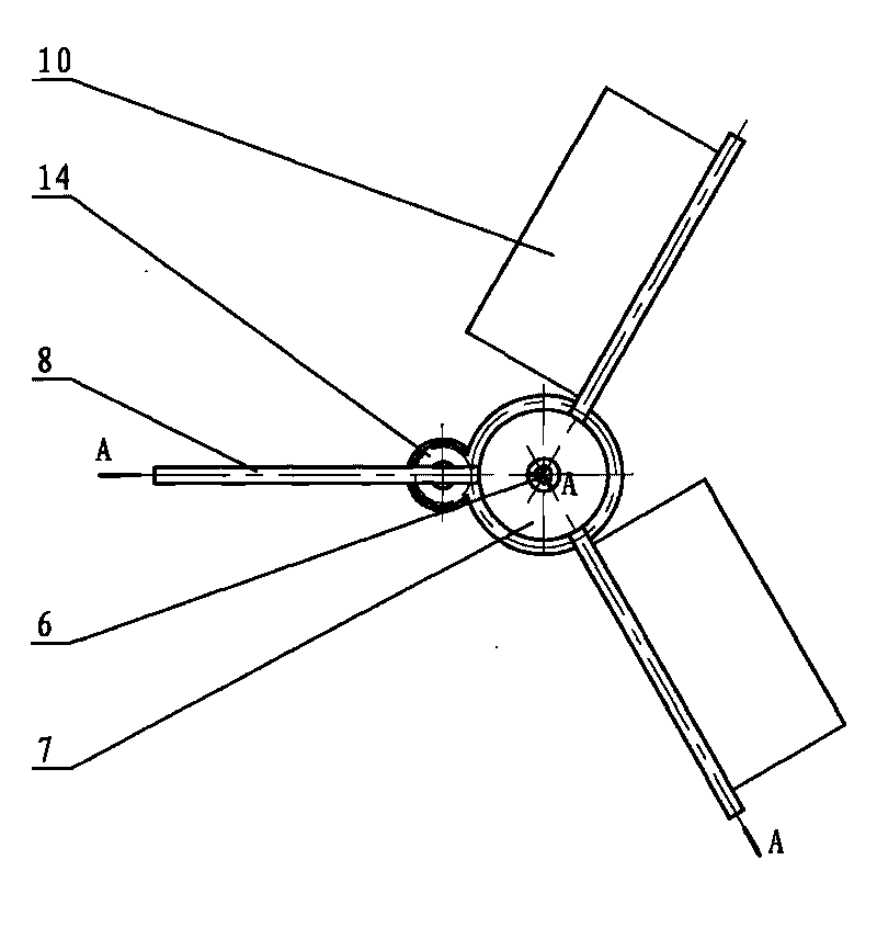
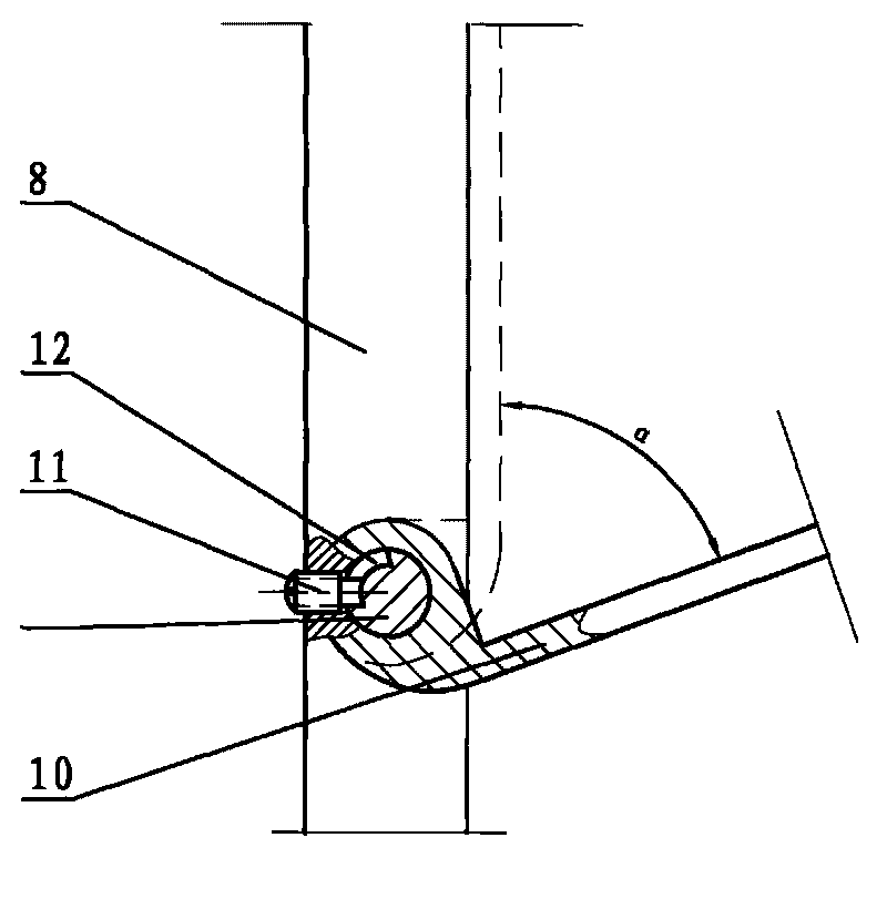
[0023] Such as Figure 1 to Figure 3 As shown, the first embodiment of the vertical flip impeller of the present invention includes a vertical support device, the vertical support device includes a main shaft 1, the lower end of the main shaft 1 is vertically fixed on the base 2, and the upper and lower ends of the main shaft 1 are equipped with rolling bearings 3, The sleeve rotor 4 is installed on the main shaft 1 through the rolling bearing 3, the sleeve rotor 4 can rotate around the main shaft 1, the thrust bearing 5 is installed between the lower end surface of the sleeve rotor 4 and the base 2, and the upper end of the main shaft 1 is passed through the fastening bolt 6 Equipped with thrust washer 7. Three sets of rotor frames 8 are fixed on the outer side of the sleeve rotor 4. Five blade shafts 9 perpendicular to the main shaft 1 are mounted on the rotor frame 8. Turning blades 10 are mounted on the blade shafts 9. The blade shafts 9 and the turning blades 10 can be po...


PUM


Abstract

The invention discloses a vertical type rotating impeller and a vertical type wind driven generator, relating to a rotating shaft and a wind driven generator perpendicular to a wind direction, and aiming at providing the wind driven generator which has simple structure, low cost, high wind energy utility ratio and wide application range. The vertical type rotating impeller comprises a vertical supporting device provided with a sleeve rotor; the sleeve rotor can rotate around the vertical supporting device; the outer side of the sleeve rotor is fixedly provided with a rotor frame; the rotor frame is provided with a plurality of mutually parallel blade shafts; the blade shafts are provided with rotating blades; the rotating blades can rotate relative to the rotor frame; when the rotor frame rotates to an upwind area along with the sleeve rotor, the rotating blades rotate to a position in an alpha plane included angle with the rotor frame along the wind direction so that both sides of the rotor frame are communicated; and when the rotor frame rotates to a downwind area along with the sleeve rotor, the rotating blades rotates to a position parallel to a plane provided with the rotor frame along the wind direction so that the rotor frame forms closed blade surfaces.

Description

technical field [0001] The invention relates to a wind power drive device, in particular to a wind power generator whose rotation axis is perpendicular to the direction of wind force. Background technique [0002] Wind resource is the most ideal green energy, inexhaustible, especially the use of wind energy for power generation. The working principle of wind power generation is mainly to use the wind force to drive the wind-driven rotor, and then the wind-driven rotor drives the rotor of a generator to rotate, thereby converting mechanical energy into electrical energy. At present, the most common wind turbines are mostly horizontal shaft type, and three sets of blades are set on the vertical plane as the wind-driven rotor. Therefore, it can only be used in areas with strong wind and stable wind direction. There are also a small number of wind turbines that use vertical shafts, but these wind turbines need to be equipped with guide plates, which take up a lot of space and ...

Claims


Application Information

Patent Timeline
IPC IPC(8): F03D3/06F03D9/00F03D9/25F03D15/00
CPCY02E10/74Y02E10/72
Inventor 周骋
Owner 周骋
Learn More