
Ankle protector

An ankle and protective gear technology, applied to protective clothing, clothing, sports accessories, etc.

Inactive Publication Date: 2010-05-26
S1 SPORT INT LTD
View PDF0 Cites 8 Cited by
  • Summary
  • Abstract
  • Description
  • Claims
  • Application Information

AI Technical Summary

Problems solved by technology

In a preferred embodiment, the ankle brace also addresses the issue of better impact protection for the user's ankle and Achilles tendon

Method used


Image

  • Ankle protector
  • Ankle protector
  • Ankle protector

Examples


Embodiment Construction

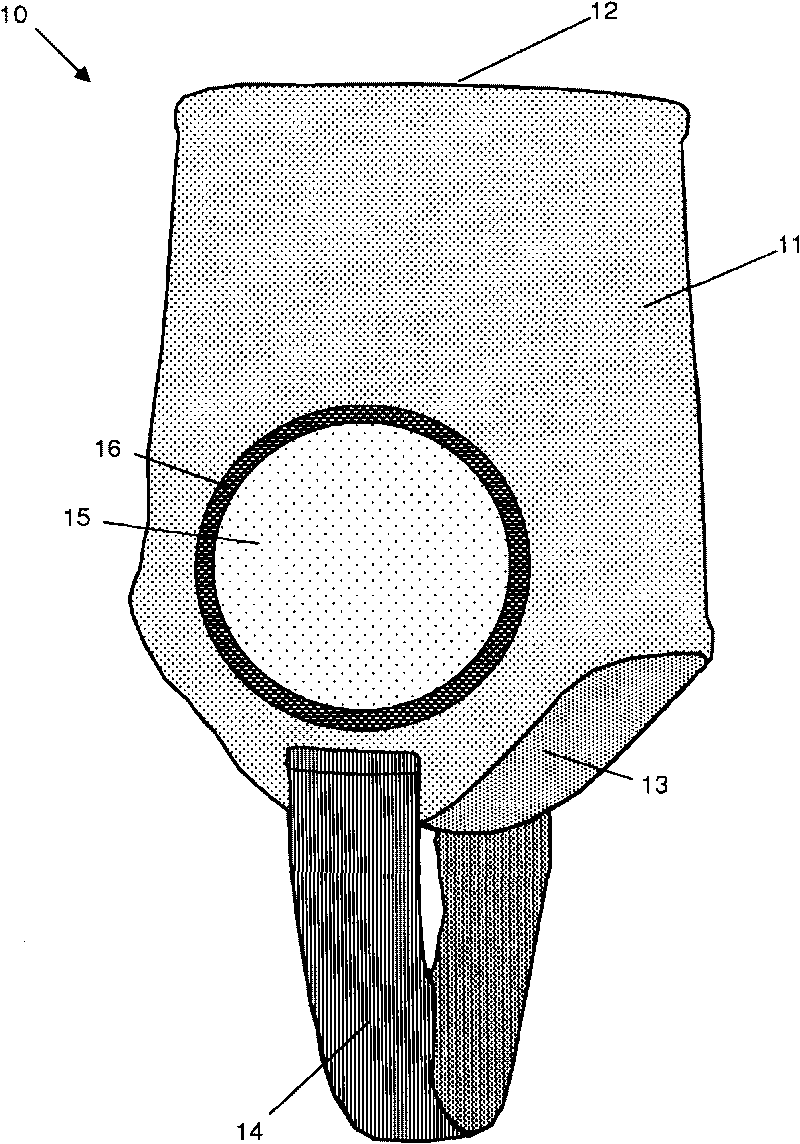
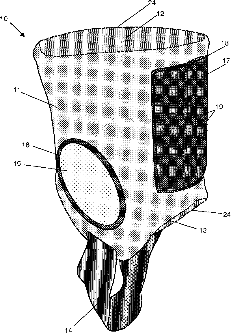
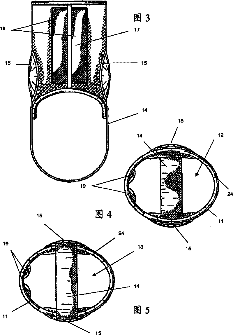
[0027] see first figure 1 , which shows the ankle brace indicated at 10 as a whole. The ankle brace 10 includes an elastic strap element 11 formed with a tubular structure made from a single piece of elastic strap material. The strap element 11 is defined by an upper hole 12 and a lower hole 13, each hole being adapted to allow the user's foot and ankle to pass therethrough when the user wears the ankle brace 11, as will be referred to hereinafter. Image 6 described in more detail.

[0028] Both the upper and lower holes 12, 13 are formed by overlock stitching the edges of the elastic band material 11 so that the holes 12, 13 have no perceptible ribs.

[0029] The ankle brace 10 is provided with a resilient stirrup 14 bridging the lower hole 13 . The stirrup 14 is designed to pass under the user's foot and hold the ankle brace 10 in place during use, and is formed from a single piece of elastic material so that there are no seams that contact the underside of the user's fo...


PUM


Abstract

An ankle protector (10) comprises an elastic webbing element (11), formed with a tubular construction thereby to surround and embrace a user's ankle region. The webbing element (11) is defined by upper and lower apertures (12, 13) to enable a user's foot (21) to pass therethrough when putting the ankle protector (10) on. Each of said upper and lower apertures (12, 13) is formed by overlock-stitching (22) an edge of the elastic webbing (11) material, such that said apertures (12, 13) have no perceptible ribs. A cushioning element (17) is attached to the webbing element (11) and is adapted to cover and protect a user's Achilles tendon. The cushioning element (17) protrudes inwardly relative to the circumference of the tubular webbing element (11).

Description

technical field [0001] The present invention relates to ankle braces. In particular, the present invention relates to an ankle brace worn over the ankle region of a user during the performance of contact sports. Background technique [0002] The invention has been developed for contact sports in general and soccer in particular. Therefore, the present invention will be described here with particular emphasis on football as an example, but it should be understood that the ankle brace of the present invention is equally applicable to other contact sports, such as rugby, American football and ice hockey, and in fact In non-contact sports, to provide protection against accidental contact with other players or equipment. [0003] The use of protective apparel by football players has become widespread at both the professional and amateur levels. Apart from the stresses and strains that are put on the player's body due to playing any sport, the most likely cause of injury during...

Claims


Application Information

Patent Timeline
Patent Type & Authority Applications(China)
IPC IPC(8): A63B71/12
CPCA63B2071/1266A63B71/1225A41D13/05A41D13/0543A63B71/12
Inventor 哈拉尔德·舍费尔罗伯特·斯蒂德
Owner S1 SPORT INT LTD
Learn More