Eureka AIR delivers breakthrough ideas for toughest innovation challenges, trusted by R&D personnel around the world.

Portable resistor-type current phase shifter

A resistive, phase shifter technology used in instruments, measuring electricity, measuring electrical variables, etc., to solve problems such as distortion, inconvenience of movement and use, and increased volume and weight

Inactive Publication Date: 2012-05-23
XUCHANG POWER SUPPLY COMPANY OF STATE GRID HENAN ELECTRIC POWER +1
View PDF0 Cites 0 Cited by
  • Summary
  • Abstract
  • Description
  • Claims
  • Application Information

AI Technical Summary

Problems solved by technology

As we all know, when there are inductance and capacitance in the line, the current with phase lag or lead can be obtained. The current technology is to use an adjustable rheostat and variable inductance coil to form a current phase shift adjustment loop. After actual use, in It can play the role of phase shifting within a certain range, which initially solves the difficulties in product testing. However, with the widespread use of this impedance line, it is exposed that there are still considerable defects, that is, the saturation of the inductance coil causes the current waveform to change. Distortion leads to distorted current waveform, which affects the quality of the test. When the power factor is adjusted below 0.9, the distortion is serious, and the actual grid power factor cannot be correctly simulated. If the principle of impedance line is still used, it is necessary to design and manufacture a special The volume and weight of the inductance coil will be greatly increased, and it will be extremely inconvenient to move and use, losing the superiority of the analog method

Method used


Image

  • Portable resistor-type current phase shifter
  • Portable resistor-type current phase shifter
  • Portable resistor-type current phase shifter

Examples


Embodiment Construction

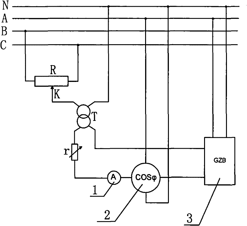
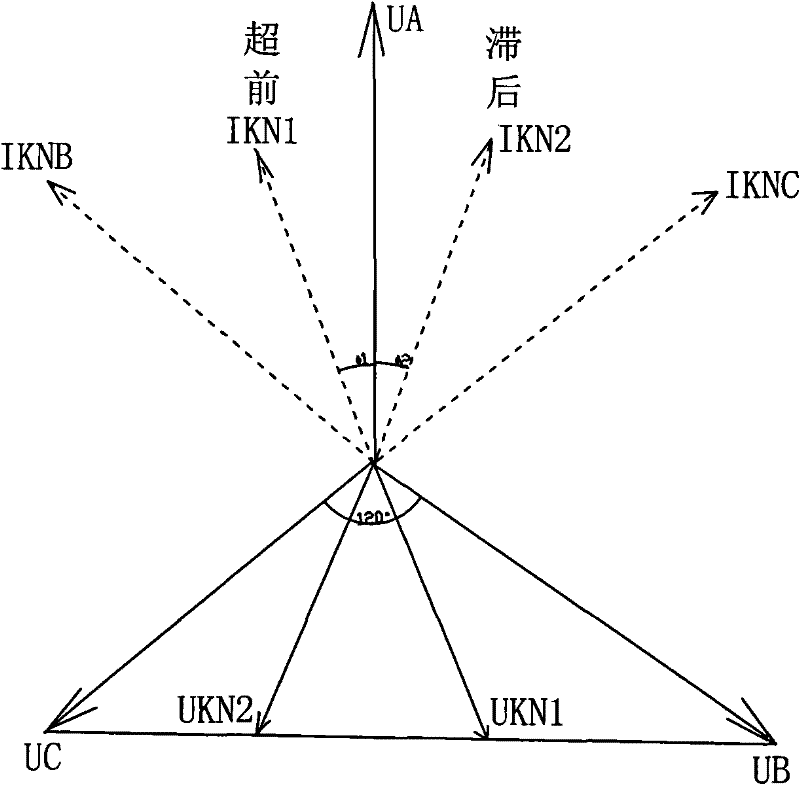
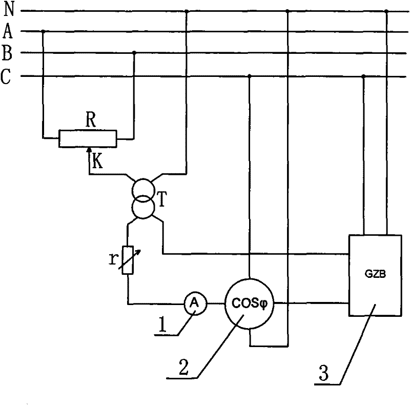
[0018] A portable resistive current phase shifter, which includes a sliding wire resistance, a transformer, a load resistance, and a power factor meter, wherein the two fixed-point joints of the sliding wire resistance are used to connect the first phase and the second phase of the three-phase grid line Between the phase lines, the sliding point joint of the sliding wire resistance is connected to the first end of the primary winding of the transformer, and the second end of the primary winding of the transformer is connected to the neutral line of the three-phase grid line, and the first end of the secondary winding of the transformer passes through the load resistor, The ammeter is connected in series with the sampling current input terminal of the power factor meter, the sampling current output terminal of the power factor meter is used to connect the sampling current input terminal of the power factor automatic compensation product to be tested, and the second terminal of th...


PUM


Abstract

The invention relates to a portable resistor-type current phase shifter. Two fixed-point connectors of a sliding resistor are used to be connected between a first phase circuit and a second phase circuit of a three-phase electric network circuit; a sliding point connector of the sliding resistor is connected with a first end of a primary winding of a transformer; a second end of the primary winding of the transformer is connected with a zero wire of the three-phase electric network circuit; a first end of a secondary winding of the transformer is connected with a sampling current input end ofa power factor meter in series through a load resistor and an ampere meter; a sampling current output end of the power factor meter is used for connecting a sampling current input end of an automaticpower factor compensating product to be tested; a second end of the secondary winding of the transformer is used for connecting a sampling current output end of the automatic power factor compensating product to be tested; sampling voltage input ends of the power factor meter and the automatic power factor compensating product to be tested are used for connecting a third phase circuit of the three-phase electric network circuit; and zero wire connecting ends of the power factor meter and the automatic power factor compensating product to be tested are used for connecting the zero wire of the three-phase electric network circuit.

Description

technical field [0001] The invention relates to the technical field of power factor test equipment, in particular to a portable resistance current phase shifter. Background technique [0002] At present, the power factor automatic compensation capacitor cabinet can maintain a certain level of power factor in the grid to achieve the purpose of saving electric energy. In order to ensure the automatic switching function of the power factor automatic compensation capacitor cabinet products, each product needs to be tested at different power factors before leaving the factory The action test under the condition is the most important test item in all tests. [0003] It is stipulated in the initial test outline that the power factor automatic compensation capacitor cabinet product should be connected to a corresponding asynchronous motor, and the power factor change can be realized by changing the motor load. This method needs to use a lot of test equipment, and the investment cos...

Claims


Application Information

Patent Timeline
Patent Type & Authority Patents(China)
IPC IPC(8): G01R31/00H02J3/18
CPCY02E40/30
Inventor 赵新卫
Owner XUCHANG POWER SUPPLY COMPANY OF STATE GRID HENAN ELECTRIC POWER
Why Eureka
Eureka Blog
Learn More