Eureka AIR delivers breakthrough ideas for toughest innovation challenges, trusted by R&D personnel around the world.

Method for light distribution of road LED illuminating lamp

A technology of LED lighting and lighting, applied in outdoor lighting, lighting devices, fixed lighting devices, etc., can solve the problems of waste of light resources, wide lighting range of lighting, unreasonable lighting design, etc.

Inactive Publication Date: 2010-05-26
CHINA MERCHANTS CHONGQING COMM RES & DESIGN INST
View PDF0 Cites 7 Cited by
  • Summary
  • Abstract
  • Description
  • Claims
  • Application Information

AI Technical Summary

Problems solved by technology

At present, there are a considerable number of roads and tunnels in my country that have unreasonable road lighting designs, and cannot select suitable lighting lamps according to the specific conditions of each tunnel, and arrange lighting lamps according to appropriate spacing; some beam angles θ are too large, and the lighting lamps The lighting range is too wide, resulting in a waste of light resources. Some beam angles θ are too small, and the lighting range of the lighting is too narrow, which cannot illuminate the entire road surface and cannot meet the lighting requirements.
At present, it is not possible to determine a reasonable beam angle of the lighting according to the tunnel conditions, and the lighting should be reasonably configured according to the beam angle
[0003] The main problem of the existing technology: it is still impossible to choose the lighting reasonably according to the tunnel conditions, and the horizontal and vertical arrangement of the lighting is unreasonable, or it causes energy waste, or cannot meet the lighting requirements

Method used


Image

  • Method for light distribution of road LED illuminating lamp
  • Method for light distribution of road LED illuminating lamp
  • Method for light distribution of road LED illuminating lamp

Examples


Embodiment Construction

[0073] The present invention will be further described in detail below in conjunction with the accompanying drawings and specific embodiments, and the tunnel is taken as an example for specific description:

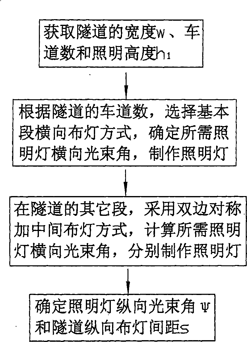
[0074] Such as figure 1 , 2 As shown, a kind of road LED lighting lamp light distribution method described in the present invention is to carry out according to the following steps:

[0075] Step 1: Measure the tunnel width w, obtain the number of lanes in the tunnel, and determine the lighting height h in the tunnel 1 , at the illumination height h 1 The following tunnel side walls and pavement require light from the lighting.

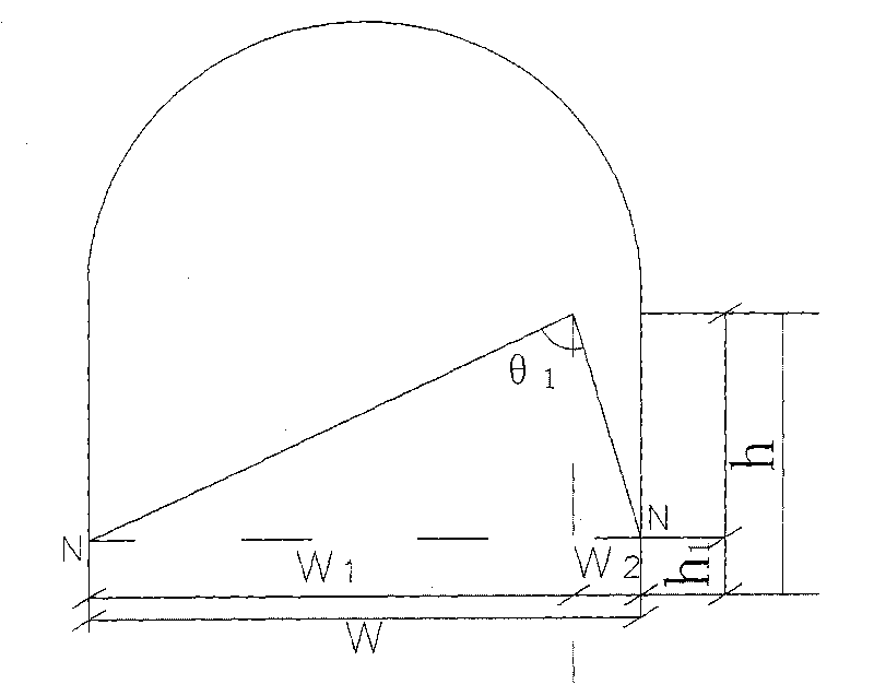
[0076] Step 2: In the basic section of the tunnel, select the horizontal lighting method according to the number of lanes in the tunnel, determine the horizontal beam angle θ of the required lighting according to the horizontal lighting method, and make the required lighting:

[0077] A: If the tunnel has two lanes, adopt the single-side ligh...


PUM


Abstract

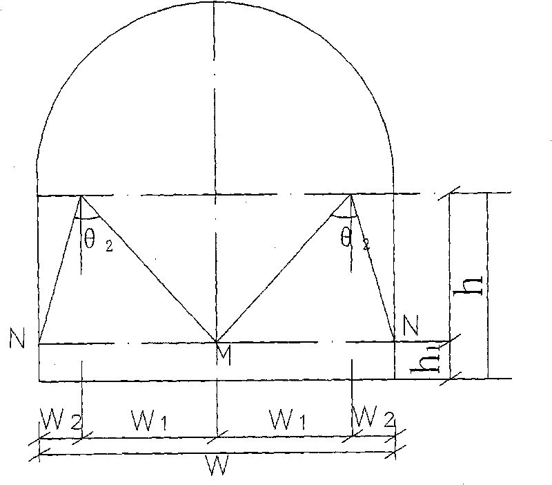
The invention relates to a method for the light distribution of a road LED illuminating lamp, which is characterized by comprising the following steps: one, measuring the width w, the lane number and the illumination height h1 of a tunnel; two, selecting a transverse lamp distribution mode at a basic section of the tunnel, determining the transverse beam angle theta, and manufacturing a needed illuminating lamp; three, adopting a bilaterally symmetrical and middle lamp distribution mode at other road sections of the tunnel, determining the transverse beam angle theta 3, and manufacturing the needed illuminating lamp according to the transverse beam angle; and four, determining the longitudinal beam angle psi of the illuminating lamp and the lamp distribution separation distance s of the tunnel. The method has the significant advantages that: the illuminating lamp can be selected reasonably according to conditions of the tunnel; the transverse and the longitudinal lamp distribution modes can be arranged reasonably; not only light resources can be used effectively, but also the requirements on illumination can be met; and the safety of pedestrians and vehicles is ensured, and simultaneously the cost can also be saved.

Description

technical field [0001] The invention relates to a light distribution method for lighting lamps, in particular to a method for determining the arrangement of LED lighting lamps for roads in tunnels. Background technique [0002] The lighting arrangement of street lights has a good visual guidance for drivers and plays a certain role in beautifying the city lighting. The lighting arrangement of roads and tunnels includes middle lighting, single-side lighting, and single-sided mid-side lighting. , Double-sided staggered lighting, bilateral symmetrical lighting and bilateral symmetrical plus middle lighting. At present, there are a considerable number of roads and tunnels in my country that have unreasonable road lighting designs, and cannot select suitable lighting lamps according to the specific conditions of each tunnel, and arrange lighting lamps according to appropriate spacing; some beam angles θ are too large, and the lighting lamps The lighting range is too wide, resulti...

Claims


Application Information

Patent Timeline
IPC IPC(8): F21S8/00G06Q50/00F21W131/103F21Y101/02F21Y115/10
Inventor 韩直
Owner CHINA MERCHANTS CHONGQING COMM RES & DESIGN INST
Why Eureka
Eureka Blog
Learn More