Yarn slack eliminating device and textile machine including the same

A slack elimination device and yarn technology, applied in spinning machines, open-end spinning machines, transportation and packaging, etc., can solve problems such as increased yarn pitch, inability to efficiently store yarns, and yarn slack

Active Publication Date: 2012-11-07
MURATA MASCH LTD
View PDF1 Cites 0 Cited by
  • Summary
  • Abstract
  • Description
  • Claims
  • Application Information

AI Technical Summary

Problems solved by technology

However, if the cone angle of the slack eliminating roller increases, the pitch of the yarn wound on the slack eliminating roller increases, and the yarn cannot be stored efficiently, resulting in an increase in the size of the slack eliminating roller.
If the cone angle is increased, the diameter difference between the upstream side and the downstream side of the slack eliminating roller increases, which also causes slack in the yarn wound on the downstream side of the slack eliminating roller
And, when the slack is too large, looping will occur and the yarn cannot be unwound

Method used


Image

  • Yarn slack eliminating device and textile machine including the same
  • Yarn slack eliminating device and textile machine including the same
  • Yarn slack eliminating device and textile machine including the same

Examples


Embodiment Construction

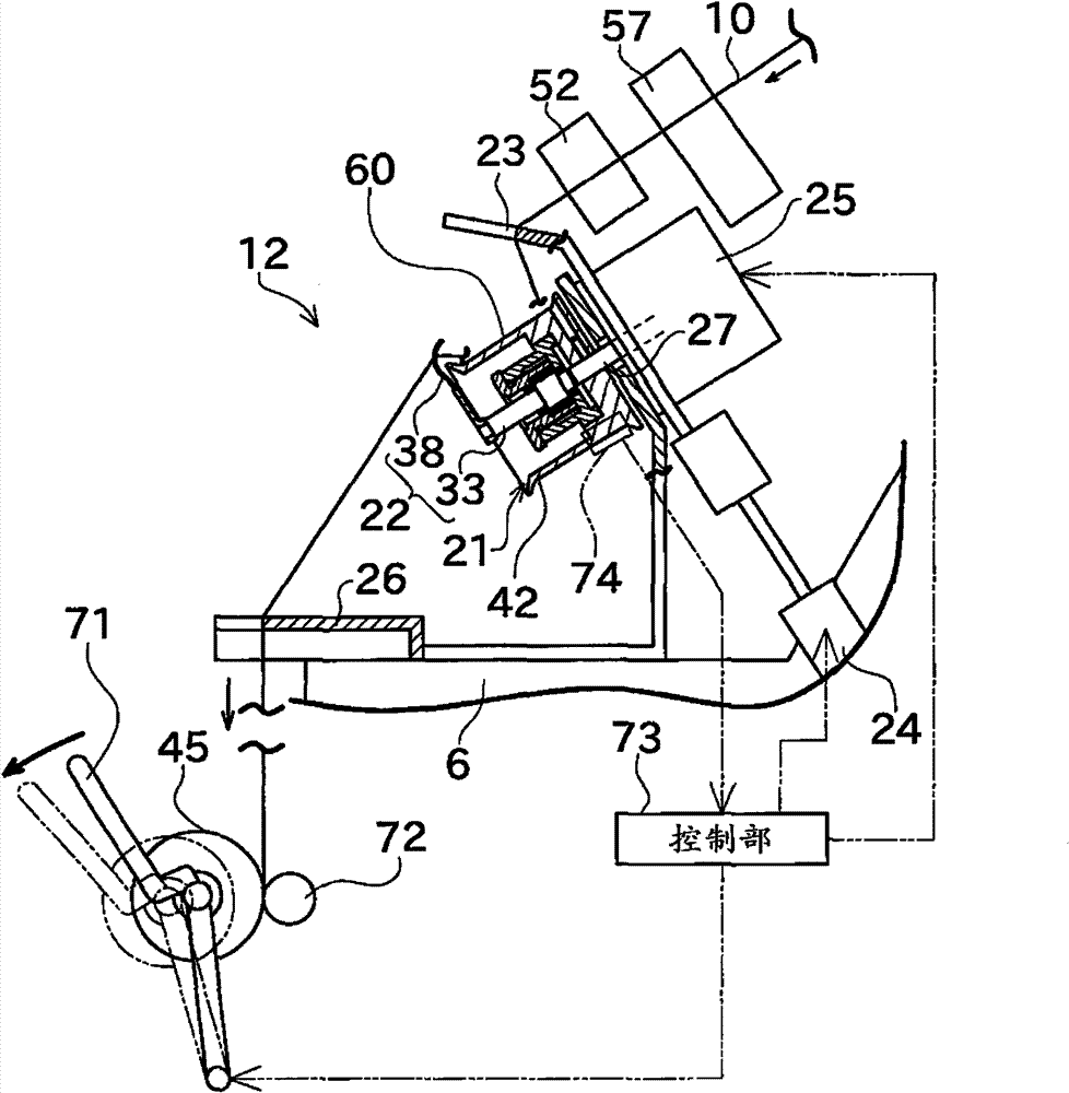
[0019] Next, preferred embodiments of the present invention will be described with reference to the drawings. Here, "upstream" and "downstream" in this specification refer to upstream and downstream in the running direction of the yarn during spinning.

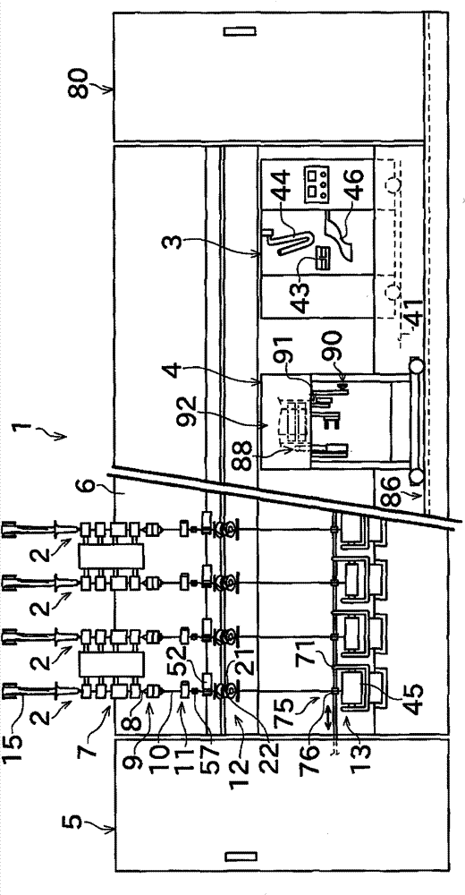
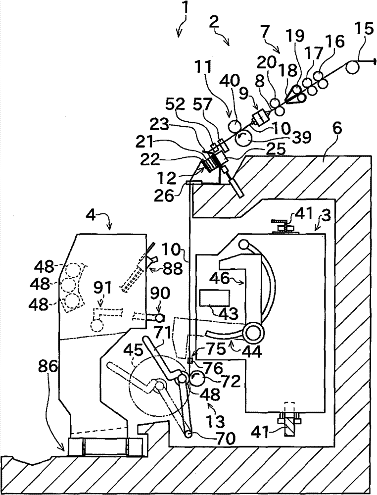
[0020] Such as figure 1 As shown, the spinning machine 1 of this embodiment includes a plurality of yarn units 2 , a piecing cart 3 , a doffing cart 4 , an air suction device (blower box) 80 , a prime mover box 5 , and a frame 6 . The spinning units 2 are arranged in parallel on the frame 6 . Each spinning unit 2 forms a package 45 of a predetermined length. Rails 41 and travel paths 86 arranged along the direction in which the spinning units 2 are arranged are provided on the frame 6 . The splicing cart 3 can travel along the rail 41 . The above-mentioned doffing vehicle 4 can travel along the above-mentioned travel path 86 .

[0021] Next, the spinning unit 2 will be described. Such as figure 1 As shown, the main stru...


PUM

PropertyMeasurementUnit
angleaaaaaaaaaa

Abstract

A yarn slack eliminating device includes a roller 42. A winding range 60 of the roller 42 around which a yarn is wound is formed in a taper shape in which a diameter decreases from an upstream side where the yarn starts to be wound around towards a downstream side. The winding range 60 includes a first taper section 62 and a second taper section 63, and a taper angle becomes moderate towards the downstream side in two stages at the first taper section 62 and the second taper section 63. An area of the first taper section 62 having a large taper angle is smaller than an area of the second taper section 63 having a small taper angle.

Description

technical field [0001] The present invention relates to a yarn slack eliminating device, and more particularly to the shape of a roller portion of the yarn slack eliminating device for storing yarn. Background technique [0002] According to the prior art, high-speed spinning machines such as air-jet spinning machines that wind spun yarns to form packages, etc., in the case of machine head operations that splice the spun spun yarns and yarns on the package side, etc. Next, control is performed to stop the winding operation on the package side. However, since the yarn continues to be sent out from the spinning device side when the winding operation is stopped, it is necessary to prevent the yarn from slack and stagnation. [0003] Therefore, in Japanese Patent Application Laid-Open No. 2006-306588, the thread slack eliminating device includes a slack eliminating roller rotationally driven by a motor, and a yarn guide member rotatable relative to the slack eliminating roller....

Claims


Application Information

Patent Timeline
Patent Type & Authority Patents(China)
IPC IPC(8): B65H51/22D01H13/00
CPCB65H2701/31B65H51/22D01H13/10D01H4/48
Inventor 冈正毅
Owner MURATA MASCH LTD
Why Eureka
Try Eureka