
Image recording apparatus

一种图像记录、设备的技术,应用在定字距的机构、印刷、打印装置等方向,能够解决墨水泄漏、电导线断裂、降低图像质量等问题

Active Publication Date: 2007-12-12
BROTHER KOGYO KK
View PDF7 Cites 15 Cited by
  • Summary
  • Abstract
  • Description
  • Claims
  • Application Information

AI Technical Summary

Problems solved by technology

Although the ink supply tube follows the reciprocating motion of the carriage while individually changing its shape, those shape changes can be disordered, that is, can be random
[0009] In cases where a sufficiently wide space cannot be provided around the flat cable and / or ink supply tubes, the reciprocating movement of the carriage can cause corresponding bending of the flat cable and ink tubes in view of the need to reduce the height and / or overall size of the image recording apparatus Partially enlarged such that the enlarged curved portion comes into contact with, and can even be damaged by, one or more surrounding members
Damage to the flat cable can cause one or more of the electrical leads contained within it to break; and damage to the ink supply tube can cause ink to leak
In addition, when the flat cable and the ink tube are in contact with surrounding members, a load may be applied to the carriage, so that the movement speed of the carriage may be made unstable, and thus the quality of the image recorded by the recording head may be degraded.

Method used


Image

  • Image recording apparatus
  • Image recording apparatus
  • Image recording apparatus

Examples


Embodiment Construction

[0041] Preferred embodiments of the present invention will be described below with reference to these drawings.

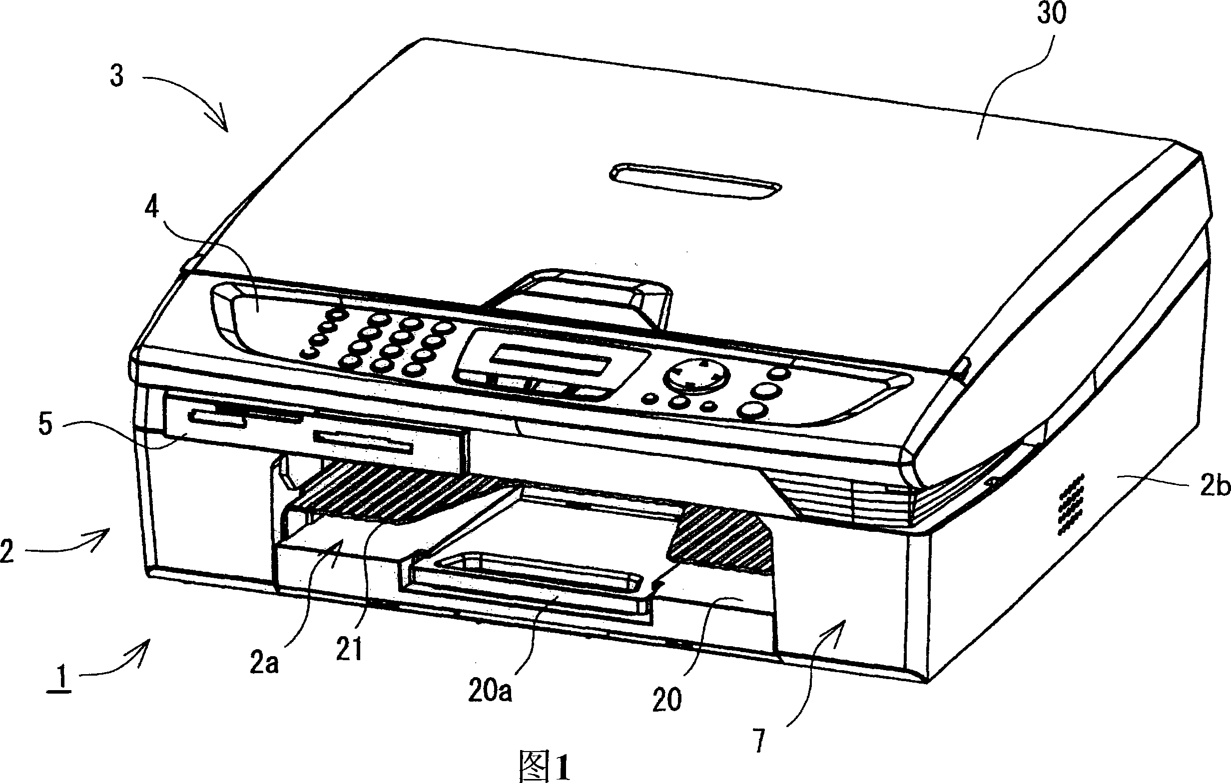
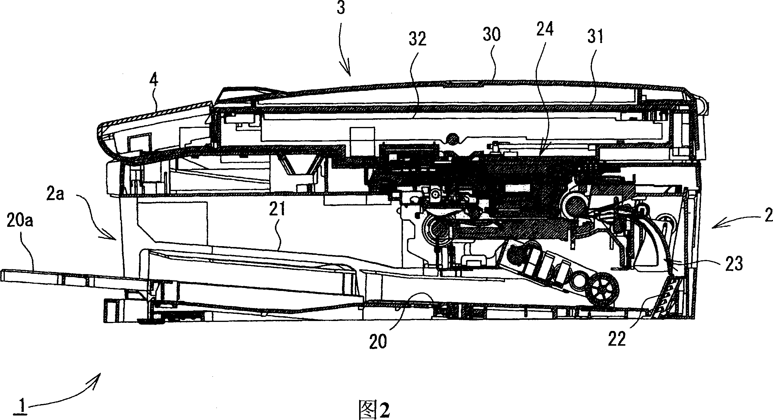
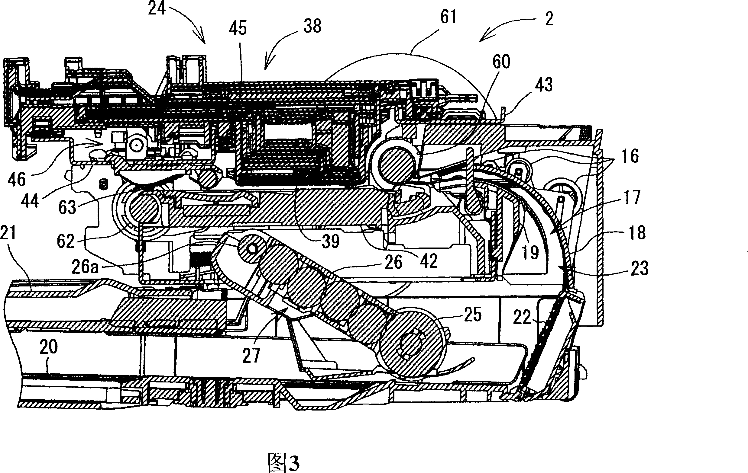
[0042] FIG. 1 shows the external structure of a multifunction device (MFD) 1 to which the present invention is applied; and FIG. 2 shows the internal structure of the MFD1. The MFD 1 includes a printer section 2 in its lower part, and additionally includes a scanner section 3 in its upper part integrated with the lower part. The MFD1 has a printer function, a scanner function, a copier function, and a facsimile function. In the present embodiment, the printer section 2 corresponds to the image recording apparatus of the present invention, and thus functions other than the printer function can be omitted. For example, the principles of the present invention are equally applicable to single function printers having only printer functionality, ie not including the scanner portion 3 or having no scanner, copier or facsimile functionality.

[0043] When the MFD1 is us...


PUM


Abstract

An image recording apparatus comprising a housing; a recording head which ejects droplets of ink; a carriage which carries the recording head and reciprocates in opposite directions and which includes a tube connection portion; an ink supply tube which is connected, at one end thereof, to the tube connection portion so as to supply the ink to the recording head, and is fixed, at a fixed portion thereof, to the housing such that an intermediate portion thereof located between the one end thereof and the fixed portion thereof forms a curved portion convex in one of the opposite directions; a pivotable support member which is pivotable about a supporting point and which includes an arm portion extending from the supporting point and having a support portion that supports the curved portion of the ink supply tube such that the curved portion is movable relative to the support portion; and a stopper member which is fixed to a predetermined portion of the ink supply tube that is located between the support portion and the tube connection portion, and which, when the ink supply tube moves relative to the support portion, engages the support portion so as to inhibit an excessive movement of the ink supply tube relative to the support portion.

Description

[0001] This application is based on Japanese Patent Application No. 2006-160067 filed on June 8, 2006, the contents of which are incorporated herein by reference. technical field [0002] The present invention relates to an image recording apparatus including a recording head that records an image on a recording medium, and a carriage that carries the recording head and reciprocates in a reciprocating direction intersecting a feeding direction in which the recording medium is fed, and More particularly, it relates to an image recording apparatus in which an ink supply tube for supplying ink to a recording head is connected to a carriage so that the ink supply tube can follow the reciprocating movement of the carriage. Background technique [0003] As for an image recording apparatus that ejects ink droplets in accordance with an input signal to record an image on a recording medium, there is known an apparatus that includes a recording head having an actuator such as a piezoe...

Claims


Application Information

Patent Timeline
Patent Type & Authority Applications(China)
IPC IPC(8): B41J2/175B41J29/00
CPCB41J2/17509B41J19/207
Inventor 佐本贤治杉浦俊夫
Owner BROTHER KOGYO KK
Learn More