
Apparatus and method for calibrating a scanning head

A technology of head and angular orientation, applied in the direction of measuring devices, instruments, etc., to achieve the effect of improving calibration accuracy and easy implementation

Active Publication Date: 2010-05-19
RENISHAW PLC
View PDF2 Cites 24 Cited by
  • Summary
  • Abstract
  • Description
  • Claims
  • Application Information

AI Technical Summary

Problems solved by technology

[0006] The disadvantage of this method is that the motorized scanning head must be precisely aligned with the calibrated rotary stage

Method used


Image

  • Apparatus and method for calibrating a scanning head
  • Apparatus and method for calibrating a scanning head
  • Apparatus and method for calibrating a scanning head

Examples


Embodiment Construction

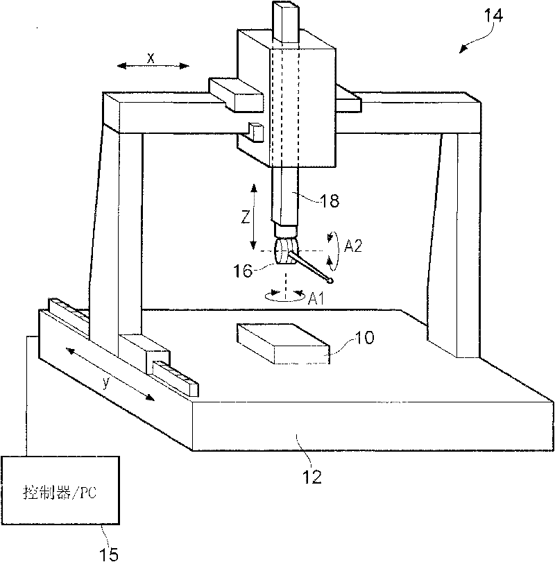
[0050] figure 1 A motor-driven scanning head is shown mounted on a coordinate locator, such as a coordinate measuring machine (CMM). The workpiece 10 to be measured is installed on the worktable 12 of the CMM 14 , and the motor-driven scanning head 16 is installed on the spindle 18 of the CMM 14 . The mandrel can be driven in the X, Y, Z directions relative to the table by means of a motor in a known manner. Other types of coordinate positioners can be used, such as machine tools, manual CMMs, or robotic arms.

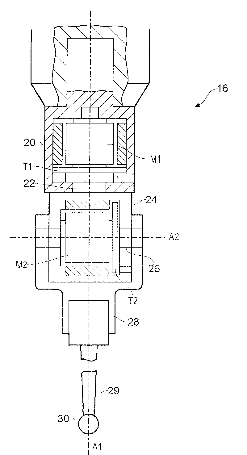
[0051] like figure 2 As shown, the motor-driven scanning head 16 comprises a stationary part formed by a base body or housing 20 which supports a movable part in the form of a shaft 22 which can be moved relative to the housing 20 about the axis A1 by means of the motor M1. turn. The shaft 22 is fastened to a further housing 24 which in turn supports a shaft 26 which is rotatable relative to the housing 24 by means of a motor M2 about an axis A2 which is perpendic...


PUM


Abstract

A method of calibrating an angular measurement scale in a motorised articulated scanning head (16) using a reference artefact (40; 60; 80) is described. The method comprises the step of rotating a surface sensing device, such as a scanning probe (28), mounted on the scanning head (16) about at least one axis (A1, A2) of the scanning head (16) to move the surface sensing device into a plurality ofdifferent angular orientations relative to the reference artefact (40; 60; 80). A step is then performed of measuring, with the surface sensing device, at least one property of the reference artefact(40; 60; 80) at each of the different angular orientations. An error map or function is then created for at least one measurement scale of the scanning head using the properties of the reference artefact (40; 60; 80) measured and optionally known or calibrated properties of that reference artefact (40; 60; 80). The method may comprise use of co-ordinate positioning apparatus, such as a co-ordinate measuring machine (14), to move the scanning head (16). The reference artefact (40; 60; 80) may comprise a single feature or an array of features (46; 66).

Description

technical field [0001] The invention relates to a device and method for calibrating a scanning head. In particular, the invention relates to a device and a method for calibrating a measurement scale in a motor-driven scanning head. Background technique [0002] It is known from International Patent Application No. WO90 / 07097 that a motor-driven scanning head can be mounted on a coordinate measuring machine. The motorized scan head allows a stylus mounted on the motorized scan head to rotate about two orthogonal axes. The stylus can be positioned angularly with respect to these two axes, while the motorized scanning head can be positioned anywhere within the working space of the instrument by means of a coordinate positioner. [0003] This motorized scan head provides a coordinate positioner with greater scanning flexibility because the motorized scan head can position the probe or stylus in many different orientations. [0004] A motor-driven scan head is capable of rotat...

Claims


Application Information

Patent Timeline
IPC IPC(8): G01B21/04
CPCG01B21/042
Inventor 琼-路易斯·格热西亚克詹姆斯·阿尔希·沙巴尼
Owner RENISHAW PLC
Learn More