Omnibearing luminous LED device

An LED device, an all-round technology, applied in the direction of electric solid-state devices, semiconductor devices, semiconductor/solid-state device components, etc., can solve the problems of no substantial technical solution to the top, divergence of light sources, and limited illuminated areas, etc. Achieving the effect of wide illumination, small size and convenient installation

Active Publication Date: 2010-05-12
DONGGUAN LIGHT SOURCE OPTO TECH
View PDF1 Cites 6 Cited by
  • Summary
  • Abstract
  • Description
  • Claims
  • Application Information

AI Technical Summary

Problems solved by technology

However, LED lights also have certain defects: due to the strong directionality of the light emitted by the LED chip, its illuminated area is limited, unlike incandescent lamps and energy-saving lamps where the light source is divergent.
[0010] The inventor of the present invention once proposed a technical solution for omni-directional LED lights, but in essence, it only emits light from the side at 360 degrees, and it does not provide a substantive technical solution for solving the top. The technical solution proposed this time is an improvement on the above Further improvement of the technical solution, a kind of omni-directional light-emitting LED device that can realize top emission at the same time is proposed

Method used


Image

  • Omnibearing luminous LED device
  • Omnibearing luminous LED device
  • Omnibearing luminous LED device

Examples


Embodiment Construction

[0026] The present invention will be described in detail below in conjunction with the accompanying drawings.

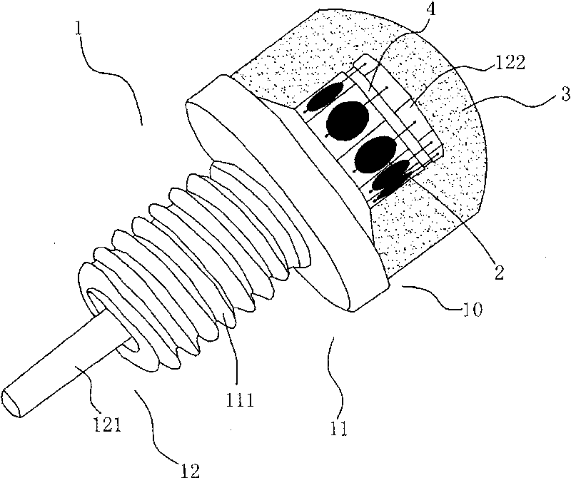
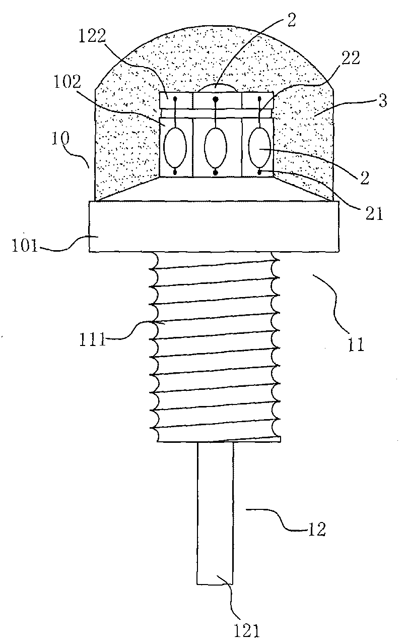
[0027] See Figure 1-5 , this embodiment includes: a bracket 1 , an LED chip 2 and a resin 3 for encapsulating the LED chip 2 .

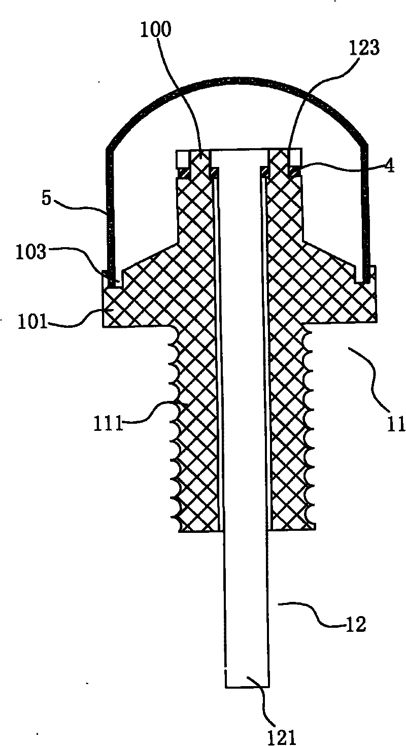
[0028] The support 1 includes: a main body 11 and probes 12 fixed to the main body 11 and insulated from each other. The main body 11 is composed of the packaging platform 10 and the threaded section 111 , and a through hole is formed in the main body 11 . Two electrode terminals 100 extending to the probes 12 are disposed on the top of the main body 11 and the packaging table 10 .

[0029] The probe 12 includes: a needle body 121 and an end 122 formed at one end of the needle body 121. The needle body 121 is inserted from the opening at the top of the packaging platform 10 and protrudes from the opening of the threaded section 111. On the end portion 122 There is a through hole 123 for the above-mentioned electrode terminal 100 to pass...


PUM


Abstract

The invention relates to the technical field of LED products, particularly relating to an omnibearing luminous LED device which comprises a holder and LED chips encapsulated on the holder by resin, wherein, the holder is provided with an encapsulation table, the LED chips are arranged around and on the top part of the encapsulation table. In the invention, a plurality of LED chips are encapsulated in one holder, and are simultaneously arranged horizontally at a 360-degree angle and on the top surface, thereby realizing omnibearing lamination and overcoming the disadvantages that top illumination is difficult to be realized in current omnibearing luminous LED products. The invention can be widely used in various luminaires; and compared with the current LED appliance, the omnibearing luminous LED device has the advantages of small volume, wide luminous orientation, convenient installation and the like.

Description

Technical field: [0001] The invention relates to the technical field of LED products, in particular to an omnidirectional light-emitting LED device. Background technique: [0002] As we all know, traditional incandescent lamps have high energy consumption and very low energy utilization rate. Only less than one tenth of the energy is converted into light energy, and the rest is wasted as heat energy. So people have been trying to find ways to replace incandescent lamps with new light sources. Therefore, energy-saving lamps came into being. Because it is relatively cheap and easy to make, it has been widely used and has a tendency to gradually replace incandescent lamps. Energy-saving lamps use the principle of electronic excitation to emit light. Compared with incandescent lamps, energy-saving lamps have the advantage of saving electricity. But one disadvantage of energy-saving lamps is that energy-saving lamps contain mercury, and mercury plays an intermediary role in en...

Claims


Application Information

Patent Timeline
Patent Type & Authority Applications(China)
IPC IPC(8): H01L25/075H01L23/13H01L23/48H01L23/10H01L23/31H01L23/482
CPCH01L2924/0002H01L2924/00
Inventor 王进
Owner DONGGUAN LIGHT SOURCE OPTO TECH
Why Eureka
Try Eureka