
Method and system for metering digital demodulation error parameters based on continuous wave combination method

A technology of digital demodulation and measurement method, applied in digital transmission system, modulation carrier system, transmission system, etc., can solve the problems of difficulty in ensuring the accuracy and reliability of the measurement process, and the lack of error parameters of digital modulation signals.

Active Publication Date: 2010-05-05
TELECOMM METROLOGY CENT OF MINIST OF IND & INFORMATION TECH +1
View PDF0 Cites 11 Cited by
  • Summary
  • Abstract
  • Description
  • Claims
  • Application Information

AI Technical Summary

Problems solved by technology

That is to say, the error parameters obtained by the current digital modulation error parameter measurement are not traceable, which makes it difficult to ensure the accuracy and reliability of the measurement process
[0004] 2. The digital modulation signal used to calibrate VSA lacks the setting of error parameters
However, the current calibration method does not set the error parameters, which is out of the actual application requirements of the digital modulation error parameters

Method used

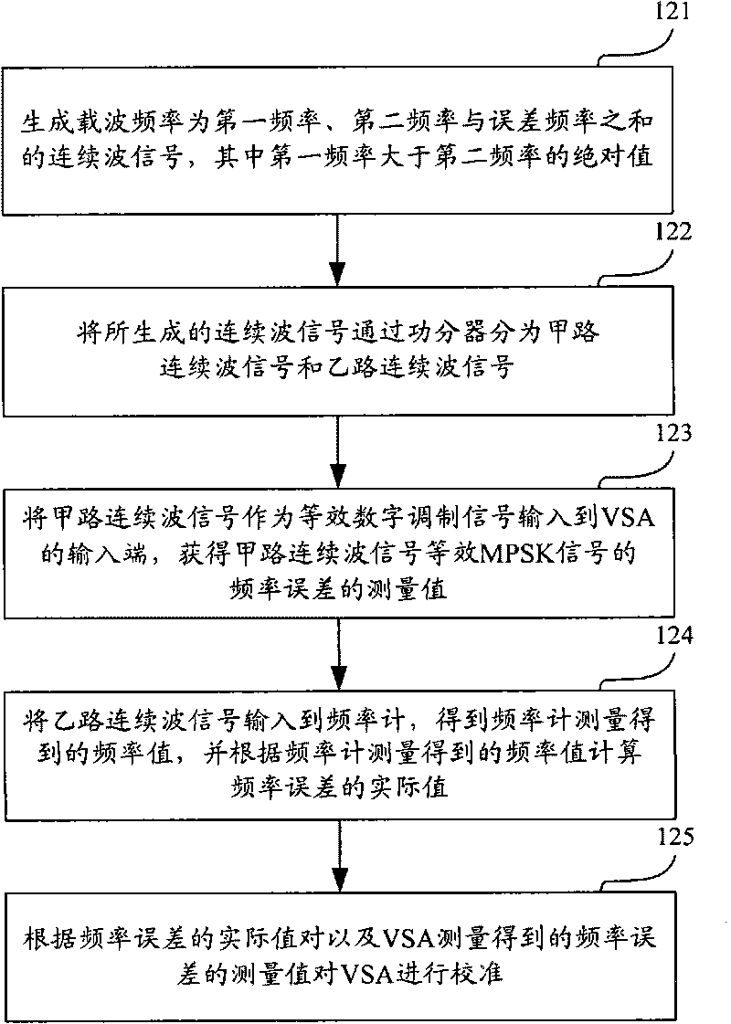
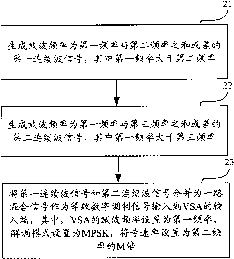

Image

  • Method and system for metering digital demodulation error parameters based on continuous wave combination method
  • Method and system for metering digital demodulation error parameters based on continuous wave combination method
  • Method and system for metering digital demodulation error parameters based on continuous wave combination method

Examples


Embodiment Construction

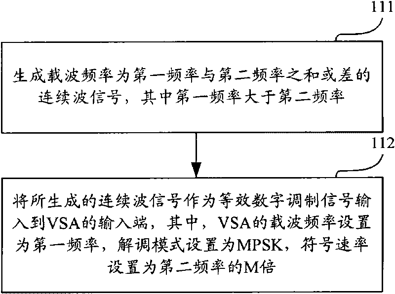
[0061] In order to solve the problem that the error parameter of the digital modulation signal generated by the existing digital signal generator is not traceable, the embodiment of the present invention provides a digital demodulation error parameter calibration method, such as figure 1 As shown, the method mainly includes:

[0062] Step 111: Generate the carrier frequency as the first frequency f d with the second frequency f b sum f d +f b or difference f d -f b The continuous wave signal C C (t), where the first frequency f d Greater than the second frequency f b ; It should be noted that, in this step, the first frequency f d and the second frequency f b are all positive.

[0063] The continuous wave signal generated by the above step 11 can be expressed by the following formula (1):

[0064]

[0065] in, for any phase value.

[0066] Step 112: Input the generated continuous wave signal as an equivalent digital modulation signal to the input terminal of t...


PUM


Abstract

The invention discloses a method and a system for metering digital demodulation error parameters based on a continuous wave combination method. The method can comprises the following steps of generating a continuous wave signal with a carrier frequency being sum or difference of a first frequency and a second frequency, wherein the second frequency is smaller than the first frequency; and inputting the generated continuous wave signal as an equivalent digital modulation signal into an input terminal of a vector signal analyzer (VSA), wherein the carrier frequency of the VSA is set to be the first frequency, a demodulation mode is set to be an M-system phase shift keying (MPSK), the symbol velocity is set to be M times of the second frequency, and M is an positive integer. In the invention, because the error parameters of the equivalent digital modulation signal for calibrating the VSA generated by the method can be precisely set and calculated, two problems that value source tracing and error setting of the digital demodulation error parameter can be synchronously solved.

Description

technical field [0001] The invention relates to the measurement of digital demodulation error parameters, in particular to a digital demodulation error parameter measurement method and system based on a continuous wave combination method. Background technique [0002] At present, digital modulation signals are the main carrier of information transmission and have become an important cornerstone of the information society. Among them, error vector magnitude root mean square value (hereinafter referred to as EvmRms), error vector magnitude peak value (hereinafter referred to as EvmPeak), amplitude error root mean square value (hereinafter referred to as MagErrRms), amplitude error peak value (hereinafter referred to as MagErrPeak), phase error mean square The root value (hereinafter referred to as PhaseErrRms), the peak value of the phase error (hereinafter referred to as PhaseErrPeak) and the frequency error (hereinafter referred to as FrequencyErr) are important error parame...

Claims


Application Information

Patent Timeline
Patent Type & Authority Applications(China)
IPC IPC(8): H04L27/00
CPCH04L27/3863
Inventor 张睿周峰王南郭隆庆卢民牛陆冰松李耀华冉志强褚文华张小雨孙景禄张媛媛牟丹冯硕赵晓昕吴镝
Owner TELECOMM METROLOGY CENT OF MINIST OF IND & INFORMATION TECH
Learn More