Remote failure diagnosis system of infrared shaft temperature detection station
A fault diagnosis system and detection station technology, applied in railway vehicle shape measuring instruments, railway car body components, railway auxiliary equipment, etc., can solve the problems of railway reputation loss, large workload and cost, train hot axle accidents, etc. The effect of compressing fault delay and compressing processing fault time
Inactive Publication Date: 2010-05-05
张永强
View PDF0 Cites 14 Cited by
- Summary
- Abstract
- Description
- Claims
- Application Information
AI Technical Summary
Problems solved by technology
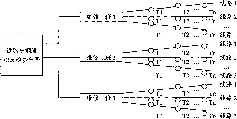
All of these tasks require maintenance personnel to carry out door-to-door maintenance of detection stations one by one along the railway line. This is a work with a large workload and cost for the maintenance unit. The railway depot will set up a 50-100 A maintenance team of one person spends millions of yuan in maintenance costs every year; it takes 1-2 hours to drive hundreds of kilometers to deal with sudden failures, and the train passing the fault detection station may have passed by when the personnel arrive. If there are 10-20 trains, if there are hot-axle cars, they cannot be found and stopped in time, which will lead to the occurrence of train hot-axle accidents, causing damage to people's lives and property, and bringing losses to the reputation of the railway.
Method used
View moreImage
Smart ImageViewing Examples
Examples
specific Embodiment
[0050] A specific embodiment of the present invention is as follows:
[0051] Such as Figure 1-Figure 21 Shown:
[0052] (1) The working principle of the host
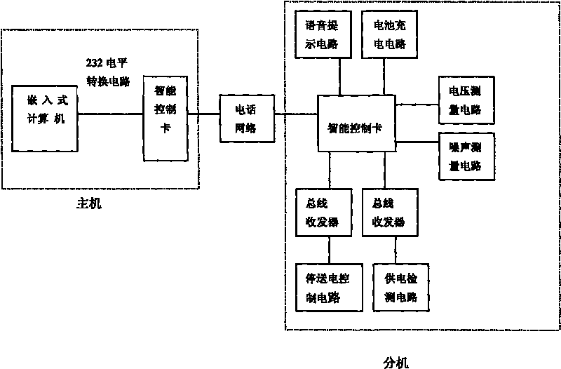
[0053] The host is composed of an embedded computer and an intelligent control card:
Login to View More PUM
 Abstract
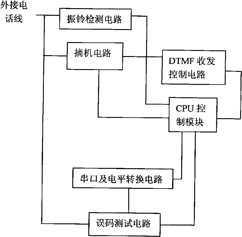
The invention relates to a remote failure diagnosis system of an infrared shaft temperature detection station, comprising a main machine and a branch machine. The main machine and the branch machine are connected by a telephone network; the main machine comprises an embedded computer and an intelligent control card; the branch machine comprises an intelligent control card, a voice prompt circuit, a power supply detection circuit, a power cut-transmission control circuit, a battery charging circuit, a voltage measurement circuit and a noise measurement circuit; detection control signaling of the system adopts the dual-tone multifrequency transport protocol; a code error test circuit realizes the remote control test of channel code error rate on a solid loop communication interface; and pseudo-random sequence codes required by the code error test are realized by adopting software mode (linear congruence algorithm). When the infrared detection station has failures, the positions of failures (power supply, communication and detection station) can be rapidly judged by using the system, and simple failure treatments (reset, power cut and power supply) are performed, thereby eliminating week detection of the maintenance of the infrared shaft temperature detection system and providing a technical support means for realizing automatic monitoring and rapid failure treatment.
Description
technical field [0001] The invention belongs to the technical field of automatic control, and in particular relates to a remote fault diagnosis system for an infrared shaft temperature detection station. Background technique [0002] The railway infrared shaft temperature detection station is a safety system for real-time detection, transmission and processing of train shaft temperature distributed along the railway line every 30 kilometers. The infrared shaft temperature detection station system consists of three parts: power supply, communication and detection station, and is installed in the unattended machine room along the railway. About 5,000 sets of infrared shaft temperature detection stations are installed on the 70,000-kilometer railway line, forming a huge infrared shaft temperature detection network covering the national railway lines to ensure the safe operation of passenger and freight trains. [0003] Such a huge train axle temperature real-time monitoring sy...
Claims
Login to View More Application Information
Patent Timeline
 IPC IPC(8): B61K9/06
Inventor 张永强
Owner 张永强
Features
- R&D
- Intellectual Property
- Life Sciences
- Materials
- Tech Scout
- Unparalleled Data Quality
- Higher Quality Content
- 60% Fewer Hallucinations
Learn More Browse by: Latest US Patents, China's latest patents, Technical Efficacy Thesaurus, Application Domain, Technology Topic, Popular Technical Reports.
© 2025 PatSnap. All rights reserved.Legal|Privacy policy|Modern Slavery Act Transparency Statement|Sitemap|About US| Contact US: help@patsnap.com


