
Portal frame movable type horizontal coordinate numerical control ultrasonic welding machine

A technology of ultrasonic welding and plane coordinates, which is applied in the field of CNC machine tools, can solve the problems of overuse of equipment, waste of processing equipment resources, low efficiency, etc., and achieve the effect of overcoming high cost

Active Publication Date: 2010-05-05
宁波市凯博数控机械有限公司
View PDF5 Cites 23 Cited by
  • Summary
  • Abstract
  • Description
  • Claims
  • Application Information

AI Technical Summary

Problems solved by technology

[0003] For the welding of workpieces with small welding surfaces, the ultrasonic welding machine of the prior art adopts manual welding and forming of the workpieces through the model welding head and fixture; Workpieces, such as large heat sinks, heat exchange fins, and honeycomb core components of automobiles, are limited by the power of the transducer and the large model welding head, and the workpiece needs to be welded point by point, segment by segment, and time-varying (according to the thickness of the solder joints) Time) welding, the existing technology lacks such special processing equipment, some enterprises adopt the method of refitting the welding head of the ultrasonic welding machine to the Z axis of general CNC cutting equipment such as "machining center", and clamping the workpiece on the movable workbench Carry out welding processing operations, so there are problems and deficiencies such as high cost, low efficiency, overkill equipment, waste of processing equipment resources

Method used


Image

  • Portal frame movable type horizontal coordinate numerical control ultrasonic welding machine
  • Portal frame movable type horizontal coordinate numerical control ultrasonic welding machine
  • Portal frame movable type horizontal coordinate numerical control ultrasonic welding machine

Examples


Embodiment Construction

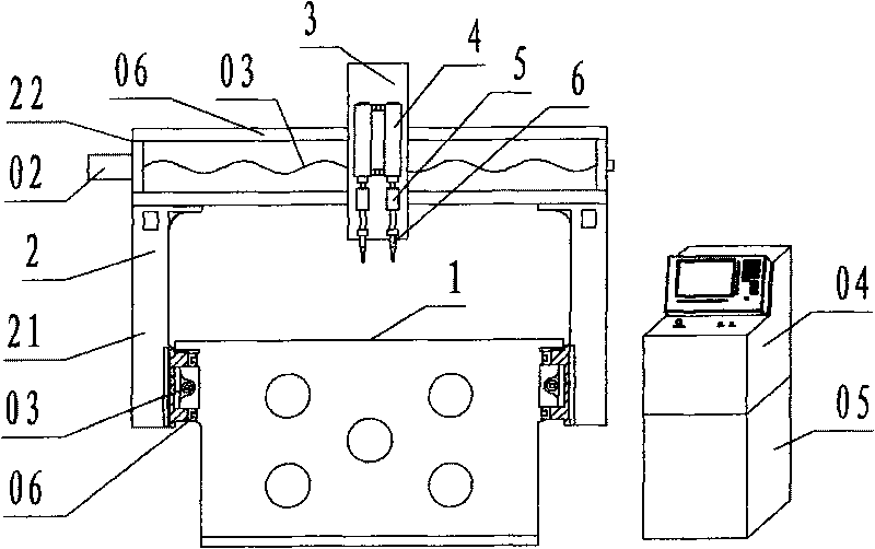
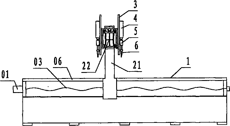
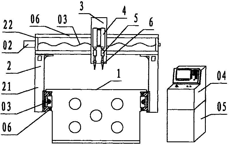
[0013] refer to Figure 1 ~ Figure 2 , a kind of gantry movable type plane coordinate numerical control ultrasonic welding machine tool of the present invention is a kind of special welding processing equipment combining ultrasonic welding machine and numerical control machine tool, including fixed workbench 1, mobile gantry 2, horizontal carriage 3, Cylinder 4, vibrator 5, welding head 6, Y-axis servo motor 01, X-axis servo motor 02, ball screw pair 03, numerical control system 04, ultrasonic generator 05, wherein: the fixed workbench 1 is a conventional machine tool The bed material is made of hollow rectangular box type, and the workbench is also the supporting part of the bed; the upper surface of the fixed workbench is a plane, and there are installation holes for setting fixtures on the plane, and the two longitudinal sides of the fixed workbench are provided with parallel, supporting parts. Guide the mobile gantry 2 to slide longitudinally, protruding grooved guide rail...


PUM


Abstract

The invention discloses a portal frame movable type horizontal coordinate numerical control ultrasonic welding machine, which is characterized by being special welding processing equipment integrated by an ultrasonic welding machine and a numerical control machine. In the invention, a box type fixed work bench and a movable portal frame are adopted in a machine structure, a controlled driving air cylinder, a high-power ultrasonic vibrator and a welding head are arranged on a transverse towing plate arranged on a portal frame beam; the high-power ultrasonic vibrator provides a vibration source, a numerical control system controls a servo motor and a screw rod system to drive the portal frame, the transverse towing plate and a horizontal coordinate target seeking according to a program, the up and down stretching of the air cylinder drives the high-power ultrasonic vibrator, and the welding head carries out welding and resetting. The invention overcomes the problems and defects of high cost, low efficiency, incomplete usage of the equipment and processing equipment resource waste; and by numerical control target seeking and automatic welding point to point and hop to hop at a variable time, the invention enables the numerical control and the automation of the ultrasonic welding of a more complex large work piece to achieve the purposes of low cost, high efficiency and high quality.

Description

technical field [0001] The invention relates to a numerical control machine tool, in particular to a gantry mobile plane coordinate numerical control ultrasonic welding machine tool which combines the technology of an ultrasonic welding machine with a numerical control machine tool and is used for high-efficiency and precise positioning welding of workpieces. Background technique [0002] Ultrasonic welding is a welding technology that transmits high-frequency vibration mechanical waves to the surfaces of two workpieces to be welded. Under pressure, the surfaces of the two workpieces are rubbed against each other to form fusion between molecular layers. It has been widely used in Surface welding of metals, welding of thermoplastics. [0003] For the welding of workpieces with small welding surfaces, the ultrasonic welding machine of the prior art adopts manual welding and forming of the workpieces through the model welding head and fixture; Workpieces, such as large heat si...

Claims


Application Information

Patent Timeline
IPC IPC(8): B23K20/10B23K20/26B29C65/08
Inventor 李恒国
Owner 宁波市凯博数控机械有限公司
Learn More