Heat dissipation equipment

A heat dissipation equipment and equipment technology, applied in the direction of cooling/ventilation/heating transformation, etc., can solve problems such as inability to adjust in real time

Inactive Publication Date: 2011-10-26
CHINA CNR CORPORATION
View PDF0 Cites 0 Cited by
  • Summary
  • Abstract
  • Description
  • Claims
  • Application Information

AI Technical Summary

Problems solved by technology

[0004] In the prior art, when the temperature of the heat-generating components in a certain cooling air duct is too high, since the air volume of the air entering the cooling air duct is fixed and cannot be adjusted in real time, it is necessary to change the air volume of the wind entering the cooling air duct , the structure of the cooling air duct must be redesigned

Method used


Image

  • Heat dissipation equipment
  • Heat dissipation equipment
  • Heat dissipation equipment

Examples


Embodiment Construction

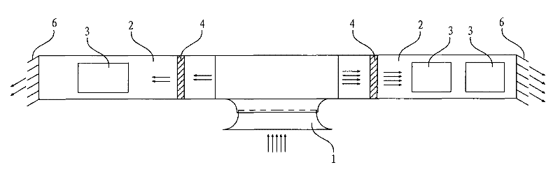
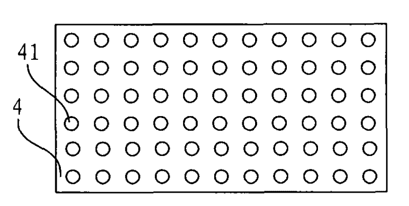
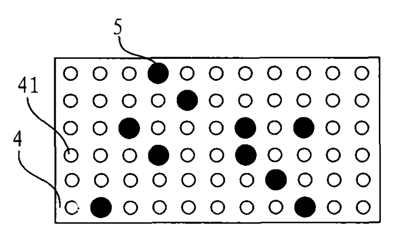
[0017] figure 1 A schematic structural diagram of a heat dissipation device provided in Embodiment 1 of the present invention, as shown in figure 1 As shown, the cooling device includes: a fan 1 , at least two cooling air ducts 2 communicating with the fan 1 , and an adjustable wind blocking plate 4 arranged at the air inlet of the cooling air duct 2 .

[0018] The heat dissipation air duct 2 is used for placing at least one heat generating component 3 . The number of cooling air ducts 2 may be multiple, and in this embodiment, two cooling air ducts 2 are taken as an example for illustration. Specifically, the cooling air duct 2 may be a sealed cooling air duct.

[0019] The fan 1 is used to provide the cooling air duct 2 with wind for reducing the temperature of the heat generating component 3 . The fan 1 can pump the wind into each cooling air duct 2, specifically because the air inlet of each cooling air duct 2 is connected with the fan 1, so the fan 1 can pump the wind ...


PUM


Abstract

The invention discloses heat dissipation equipment, which comprises a fan, at least two heat dissipation air ducts communicated with the fan, and adjustable wind resistance baffle plates arranged at wind inlets of the heat dissipation air ducts. The heat dissipation air ducts are used for placing at least one heating component; the fan is used for providing wind for the heat dissipation air ductsto reduce the temperature of the heating component; and the adjustable wind resistance baffle plates are used for adjusting the quantity of the wind entering the heat dissipation air ducts. The heat dissipation equipment in the embodiment of the invention comprises the fan, the at least two heat dissipation air ducts communicated with the fan, and the adjustable wind resistance baffle plates arranged at the wind inlets of the heat dissipation air ducts, so the quantity of the wind entering the heat dissipation air ducts can be adjusted through the adjustable wind resistance baffle plates; therefore, when the quantity of the wind entering one of the heat dissipation air ducts needs to be changed, the change of the quantity of the wind entering the heat dissipation air ducts can be implemented only by adjusting the adjustable wind resistance baffle plate, and the structures of the heat dissipation air ducts are prevented from being redesigned.

Description

technical field [0001] The invention relates to the technical field of heat dissipation, in particular to a heat dissipation device. Background technique [0002] Power electronic equipment includes various heat-generating components, for example, the heat-generating components may be reactors, transformers, or power switch tubes installed with radiators. Due to the limited installation space in electronic power equipment, the volume of heat-generating components such as power switch tubes, reactors, and transformers cannot be too large. Therefore, natural ventilation and heat dissipation for heat-generating components cannot meet the heat dissipation requirements. Forced ventilation and heat dissipation for heat-generating components are required to meet heat dissipation requirements. need. In electronic power equipment, the maximum temperature that various heating components can withstand is different, even very different. For example, the iron core or coil of a transfor...

Claims


Application Information

Patent Timeline
Patent Type & Authority Patents(China)
IPC IPC(8): H05K7/20
Inventor 戴碧君车向中张宇李岩孔东晓
Owner CHINA CNR CORPORATION
Why Eureka
Try Eureka