Eureka AIR delivers breakthrough ideas for toughest innovation challenges, trusted by R&D personnel around the world.

Fan, nitrogen generation equipment and control method of nitrogen generation equipment

A control method and fan technology, which are applied in pump control, mechanical equipment, engine control, etc., can solve the problems of high power consumption, large heat production, fan power consumption, etc. The effect of large cooling air volume and reducing driving power

Active Publication Date: 2022-03-08
YANTAI JEREH PETROLEUM EQUIP & TECH CO LTD
View PDF9 Cites 0 Cited by
  • Summary
  • Abstract
  • Description
  • Claims
  • Application Information

AI Technical Summary

Problems solved by technology

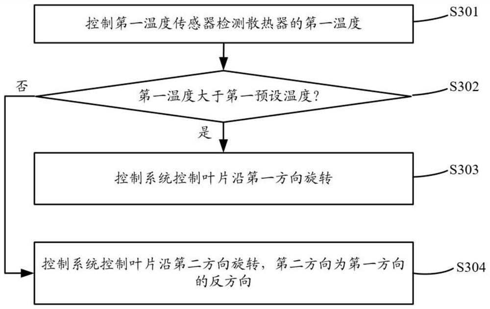
[0003] The heat production of nitrogen-generating equipment is related to the size of the equipment load. If the equipment load is large, the heat production will be large, and if the equipment load is small, the heat production will be small. When the equipment load is large or the equipment load is small, the power consumed by driving the fan is constant. In this way, when the equipment load is small, the fan will generate unnecessary power consumption, which will cause the cooling device of the nitrogen generating equipment to lose power. High consumption

Method used


Image

  • Fan, nitrogen generation equipment and control method of nitrogen generation equipment
  • Fan, nitrogen generation equipment and control method of nitrogen generation equipment
  • Fan, nitrogen generation equipment and control method of nitrogen generation equipment

Examples


Embodiment Construction

[0024] The following will clearly describe the technical solutions in the embodiments of the present application with reference to the drawings in the embodiments of the present application. Obviously, the described embodiments are part of the embodiments of the present application, but not all of them. All other embodiments obtained by persons of ordinary skill in the art based on the embodiments in this application belong to the protection scope of this application.

[0025] The terms "first", "second" and the like in the specification and claims of the present application are used to distinguish similar objects, and are not used to describe a specific sequence or sequence. It should be understood that the terms so used are interchangeable under appropriate circumstances such that the embodiments of the application can be practiced in sequences other than those illustrated or described herein, and that references to "first," "second," etc. distinguish Objects are generally o...


PUM


Abstract

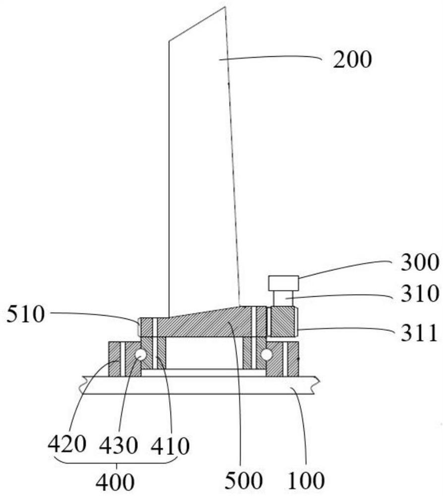
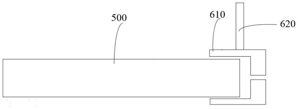
The invention discloses a fan, nitrogen making equipment and a control method of the nitrogen making equipment, and belongs to the technical field of nitrogen making equipment. The fan comprises an impeller, blades, a first driving mechanism and a second driving mechanism, the blades are rotatably connected to the impeller, the first driving mechanism is in driving connection with the impeller so as to drive the impeller to drive the blades to rotate, and the second driving mechanism is in driving connection with the blades so as to adjust the included angle between the blades and the impeller by driving the blades to rotate. According to the scheme, the problem of relatively high power consumption of a heat dissipation device of nitrogen generation equipment in the related technology can be solved.

Description

technical field [0001] The application belongs to the technical field of nitrogen-generating equipment, and in particular relates to a fan, nitrogen-generating equipment and a control method for nitrogen-generating equipment. Background technique [0002] The heat dissipation device of the nitrogen making equipment includes a radiator and a fan. The fan rotates to drive the airflow, and the airflow flows through the radiator, which can carry the heat in the radiator to the outside of the nitrogen making equipment to realize the heat dissipation of the nitrogen making equipment. [0003] The heat production of nitrogen-generating equipment is related to the size of the equipment load. If the equipment load is large, the heat production will be large, and if the equipment load is small, the heat production will be small. When the equipment load is large or the equipment load is small, the power consumed by driving the fan is constant. In this way, when the equipment load is sm...

Claims


Application Information

Patent Timeline
Patent Type & Authority Applications(China)
IPC IPC(8): F04D25/08F04D27/00F04D29/36
CPCF04D25/08F04D27/00F04D27/002F04D29/362F05D2270/303
Inventor 袁圣杰连开武刘元良吴义朋王震威刘有仓李平
Owner YANTAI JEREH PETROLEUM EQUIP & TECH CO LTD
Why Eureka
Eureka Blog
Learn More