
Solar cell

A technology of solar cells and top cells, applied in the field of solar cells, can solve the problems of high technical and process complexity, high photo-induced degradation rate of cells, complicated cell process, etc., achieve low photo-induced degradation rate and reduce photo-induced degradation rate , The effect of simple production process

Active Publication Date: 2010-04-21
ENN SOLAR ENERGY
View PDF0 Cites 7 Cited by
  • Summary
  • Abstract
  • Description
  • Claims
  • Application Information

AI Technical Summary

Problems solved by technology

But for battery manufacturing, the more layers there are, the higher the technical and process complexity
[0005] In summary, the existing technology not only makes the process complicated due to the structural problems of the battery, but also the light-induced degradation rate of the battery is still high

Method used


Image

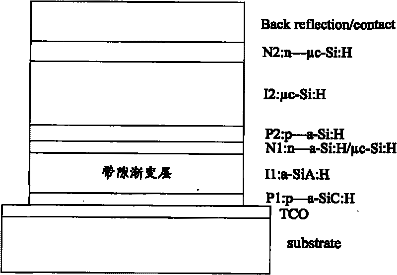
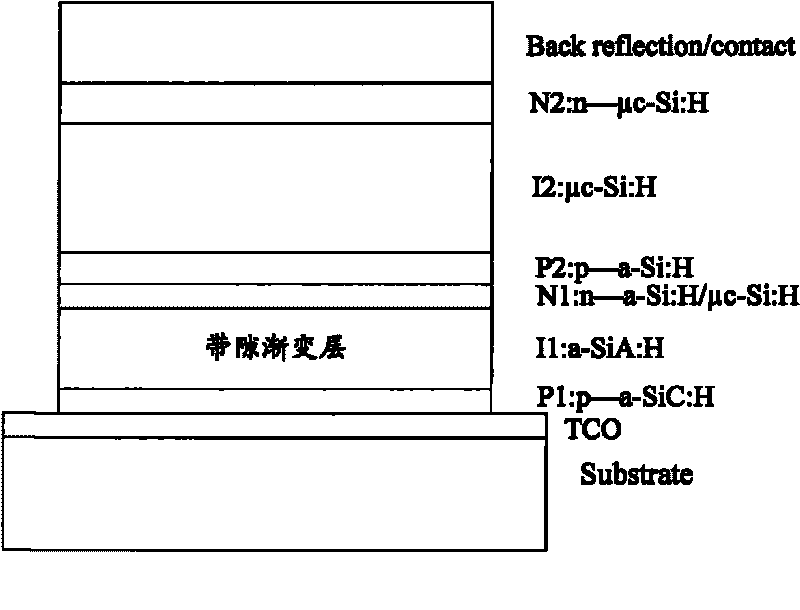
  • Solar cell
  • Solar cell
  • Solar cell

Examples


Embodiment Construction

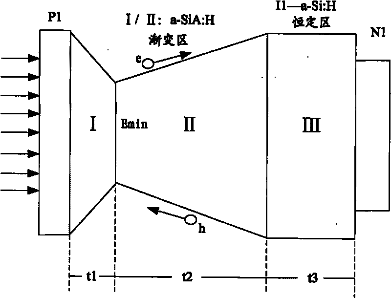
[0020] In the embodiment of the present invention, the band gap is gradually changed in the I layer of the top battery unit of the double-junction laminated battery, and the thickness of the I layer is reduced by reducing the band gap, thereby reducing the light-induced degradation rate and improving the stability of the battery.

[0021] see figure 1 , the solar cell in this embodiment includes two cells, a top cell and a bottom cell. The top cell includes the material a-Si:H, and may also include the alloy a-SiA:H (A represents elements such as Ge, C, O, etc.), and the bottom cell includes the material μc-Si:H. The top cell includes a P1 layer, an I1 layer, and an N1 layer. The bottom cell includes a P2 layer, an I2 layer, and an N2 layer. The solar cell also includes a transparent conductive film (TCO), a back reflection electrode (Back reflection / contact) and a substrate (Substrate).

[0022] The I1 layer is a graded band gap layer. In this embodiment, the thickness of...


PUM

PropertyMeasurementUnit
Thicknessaaaaaaaaaa
Thicknessaaaaaaaaaa
Total thicknessaaaaaaaaaa

Abstract

The invention discloses a solar cell for realizing low photo-induced fading rate, wherein the solar cell comprises alpha-SiA:H / mu c-Si:H bi-node laminated cell unit (A represents elements, such as G3, C and O), wherein layer I of a top cell unit is thinned and adopts design of gradually changing energy band, so that spectral response of the top cell expands to a long wave as the spectral response of a bottom cell expands to a short wave. Therefore, the thicknesses of the top cell and the bottom cell are greatly reduced, and the photo-induced fading rate and cost are lowered.

Description

technical field [0001] The invention relates to the field of batteries, in particular to solar batteries. Background technique [0002] Silicon-based thin-film batteries have the characteristics of large-area preparation, high power generation, and low cost. However, due to the existence of the SW (abbreviation of two names) effect, the development of this type of battery has been greatly affected. [0003] In order to solve this problem, various solutions are adopted in the prior art. The first solution: adding a reflective layer to the double-junction laminated battery. That is, a reflective layer is added between the top cell and the bottom cell of the a-Si:H / μc-Si:H double junction stack cell structure. Present reflection layer material comprises metal oxide (as indium tin oxide ITO and silicon oxide etc.), although this method can thin I layer, the shortcoming of this scheme is that the preparation of this intermediate reflection layer material is more difficult, and...

Claims


Application Information

Patent Timeline
IPC IPC(8): H01L31/042H01L31/0248
CPCY02E10/52Y02E10/50
Inventor 于振瑞张晓勇王凌云
Owner ENN SOLAR ENERGY
Learn More