T-shaped burning beam
A technology for burning beams and beams, applied in burners, lighting and heating equipment, etc., can solve the problems of increasing equipment investment and maintenance costs, easily burning out the burner port, affecting normal production, etc., and saving equipment investment and maintenance. cost, improve product quality, reduce and avoid the effect of local over-burning or burning
- Summary
- Abstract
- Description
- Claims
- Application Information
AI Technical Summary
Problems solved by technology
Method used
Image

Examples
Embodiment 1
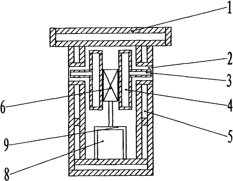
[0017] The "T"-shaped combustion beam of the present invention is composed of a beam body 1, in which a fuel pipeline 4 and an air channel 8 are arranged, and burners 2 are arranged on both sides of the beam body, with 10 burners on each side, and the burners include extended Type fuel nozzle 3 and air outlet, the fuel nozzle 3 extends into the burner mouth, and the fuel pipeline is connected to the fuel nozzle. The air outlet is a gap around the fuel nozzle and communicates with the air passage. Two fuel pipelines are arranged in the beam body, and the fuel pipeline is a rectangular box-shaped body structure. The two fuel pipelines are fixedly installed in the air passage with a fixing piece 6, and the fixing piece is supported by a bracket 9. Each fuel pipeline is connected to The fuel nozzle of the burner on the same side, the fuel nozzle is inserted into the burner port. A cavity 5 through which a cooling medium circulates is provided between the inner wall and the outer ...
Embodiment 2
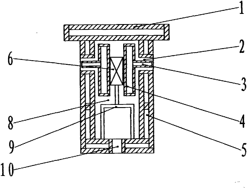
[0020] Another solution of the present invention is as figure 2 As shown, the lower part of the beam body is provided with 10 air nozzles 10 , and the air channel is connected to the air outlet of the burner 2 and the air nozzles 10 . The two fuel pipelines are fixedly installed in the air passage with the fixing piece 6 , and the fixing piece is supported with the bracket 9 . Other structures are the same as in Embodiment 1.
[0021] The supplementary combustion-supporting air sprayed from the air nozzle 10 at the lower part of the combustion beam disperses and flows upward under the suction action of the suction beam at the upper part of the kiln body, and continues to burn with the incompletely burned fuel. To reduce the intensity of fuel combustion at the outlet of the burner and improve the uniformity of the calcined product.
Embodiment 3
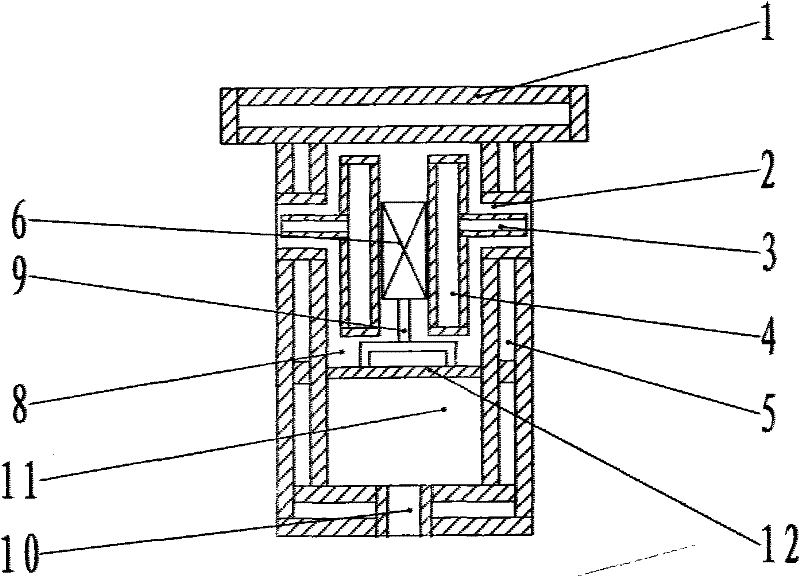
[0023] Yet another embodiment of the present invention is as image 3 As shown, the lower part of the beam body is provided with 10 air nozzles 10, and the beam body is divided into upper and lower two air passages 8, 11 by a partition 12. The fuel pipeline 4 passes through the upper air passage 8 and communicates with the air outlet of the burner, and the lower air passage 11 communicates with the air nozzle 10 . Other structures are the same as in Embodiment 1.
[0024] The supplementary combustion-supporting air sprayed from the air nozzle 10 at the lower part of the combustion beam disperses and flows upward under the suction action of the suction beam at the upper part of the kiln body, and continues to burn with the incompletely burned fuel. Control the pressure entering the upper air passage 8 to be lower than the pressure of the lower air passage 11, so that the amount of air ejected from the burner is lower than the theoretical value required for combustion, and the ...
PUM
 Abstract
Description
Claims
Application Information
 - R&D
- Intellectual Property
- Life Sciences
- Materials
- Tech Scout
- Unparalleled Data Quality
- Higher Quality Content
- 60% Fewer Hallucinations
Browse by: Latest US Patents, China's latest patents, Technical Efficacy Thesaurus, Application Domain, Technology Topic, Popular Technical Reports.
© 2025 PatSnap. All rights reserved.Legal|Privacy policy|Modern Slavery Act Transparency Statement|Sitemap|About US| Contact US: help@patsnap.com